Keywords
|
| ADS, Conversion Gain, Gilbert Mixer, Noise Figure. |
INTRODUCTION
|
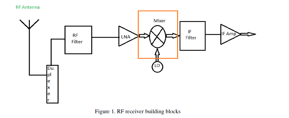
| RF Mixer is a 3-port active or passive device is designed to yield, a sum and a difference of frequencies at a single output port when two distinct input frequencies are inserted into the other two ports. A common misunderstanding about mixers is that a Mixer is only a nonlinear device. Actually an RF Mixer is fundamentally a linear device, which is shifting a signal from one frequency to another, keeping (faithfully) the properties of the initial signal (phase and amplitude), and therefore doing a linear operation. From the moment that we use a nonlinear device to perform the mixing operation, Mixers have relatively high levels of intermodulation distortion, spurious responses, and other undesirable nonlinear phenomena. In contrast to frequency multipliers and dividers, which also change signal frequency, mixers theoretically preserve the amplitude and phase without affecting modulation properties of the signals at its ports. |
 |
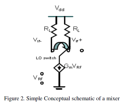
| Mixers generally have a gain stage, a switching stage, and a differential IF output such as the one shown in Figure 2. The current in the RF frequency is amplified by the gain stage at the bottom of the circuit. The current is then steered to one side of the output or the other depending on the value of the LO. The result is a mixing of the LO and RF frequencies. |
 |
| It is well known that linear, time-invariant systems are not able to produce outputs with spectral components that are not present at the input. That is, in order to perform frequency translation, the circuits used as mixers must be either nonlinear or time varying. Although the techniques used to realize mixing are quite different for different mixer topologies, the essence of all mixers lies in the concept of multiplying two signals in the time domain. Suppose that the two input signals of the mixer are |
| X (t) = A cos(ω1t) and |
| Y (t) B cos(ω2t) |
| The multiplication can be expressed as the following equation |
 |
SYSTEM ARCHITECTURE
|
| A System Block Diagram |
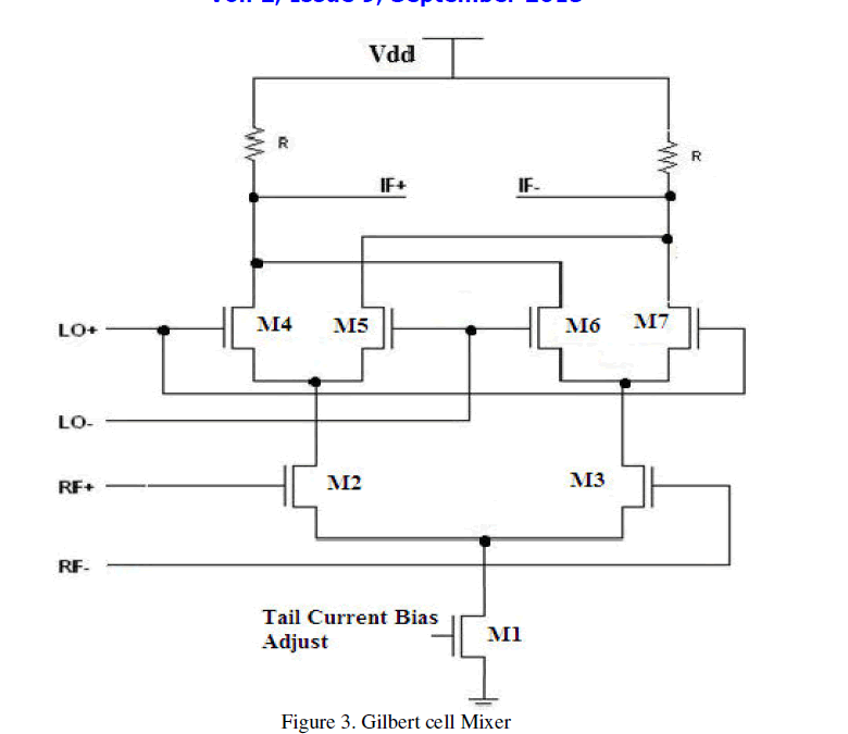
| The Figure 3 shows traditional Gilbert Cell mixer shows The RF signal is applied to the transistors M2 & M3 which perform a voltage to current conversion. For corrects operation these devices should not be driven into saturation and therefore, signals considerably less than the 1dB compression point should be used. Performance can be improved by adding degeneration resistors, on the source terminals of M2 & M3. MOSFET M4 to M7 form a multiplication function, multiplying the linear RF signal current from M2 and M3 with the LO signal applied across M4 to M7 which provide the switching function. M2 and M3 provide +/- RF current and M4 & M7 switch between them to provide the RF signal or the inverted RF signal to the left hand load. M5 & M7 switch between them for the right hand load. The two load resistors form a current to voltage trans-formation giving differential output IF signals. |
 |
| B Source Degeneration |
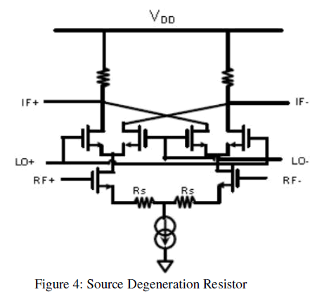
| An important mixer requirement is linearity. There are several ways to increase linearity such as increasing the voltage supply or increasing the current. However, the most common and effective method to improve linearity is to use some type of source degeneration. Figure 4 shows the mixer with source degeneration resistors and Figure 5 with source degeneration inductors. Resistors are used when the size of the circuit needs to be minimized. Inductor degeneration is usually preferred because it has no thermal noise to degrade the noise Figure, and it saves headroom because there is no voltage drop across it. In the design, resistor degeneration was used because the circuit must operate over a broad bandwidth. [7]. |
 |
 |
MIXER ANALYSIS
|
| C Design Steps of Gilbert Mixer |
| Due to complexity of the signals in today’s digital communications, proper Mixer design is crucial for solutions. Design procedure or steps are different according to designer or transceiver but commonly used steps are as follows:c |
| ïÃâ÷ Selection of Transistor |
| ïÃâ÷ DC Biasing |
| ïÃâ÷ Gain |
| ïÃâ÷ Noise Figure |
| ïÃâ÷ Linearity |
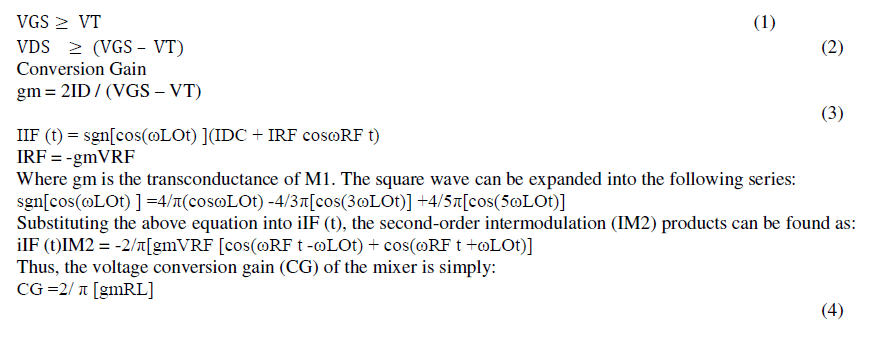
| All transistors are to operate in the saturation region. For this requirement to be met, two expressions must be satisfied once these conditions have been satisfied it is possible to approximate the transistor behaviour in the saturation region through the following equation. |
 |
MIXER PERFORMANCE
|
| D Noise Figure |
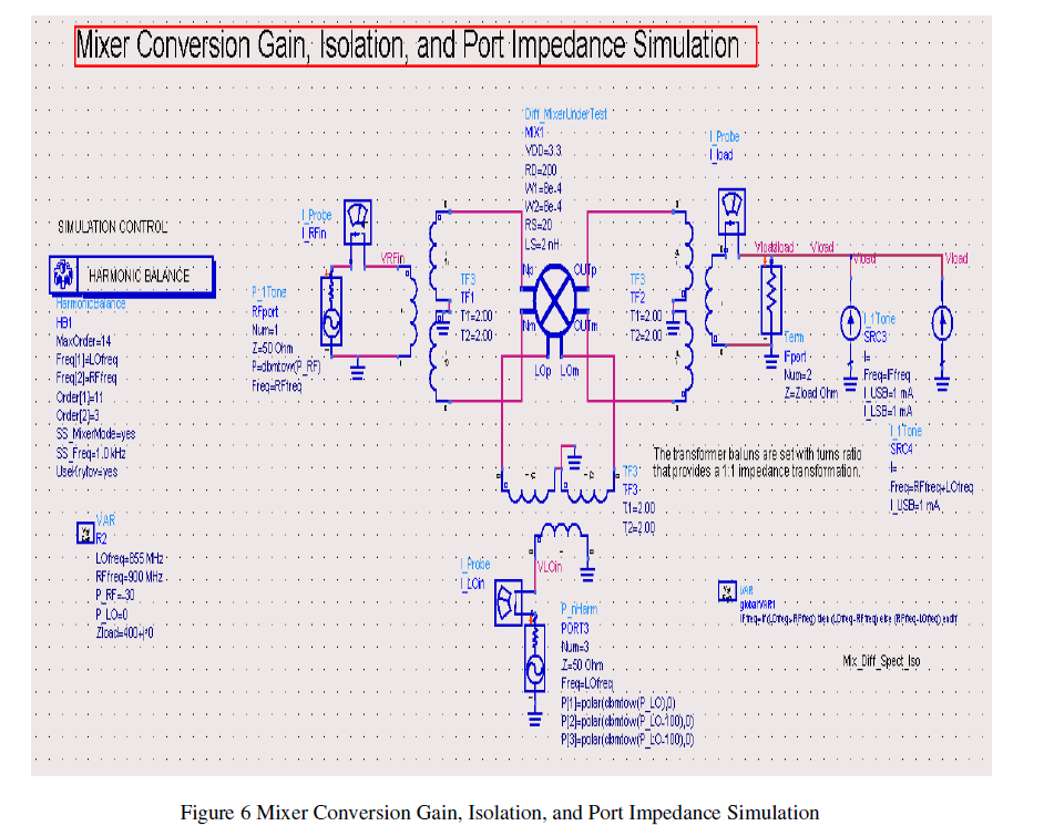
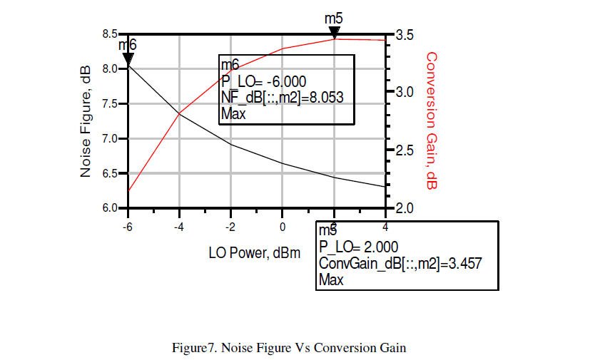
| Figure 6 shows Noise Figure Vs Conversion Gain Simulation simulates "All Sideband" (DSB) NF since all images are included in noise and conversion gain calculation. This is identical to the Hot-Cold measurement technique used by most noise figure measurement systems. Figure 7 shows the output of noise figure, conversion gain with Local oscillator power. |
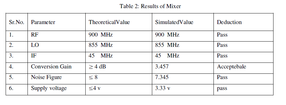
| The noise figure gets worse if more harmonics of the LO source are added, or if their power levels are set higher, here in this mixer noise figure simulation LO power is set to Noise generated due to each component available in proposed Gilbert mixer is simulated and as shown in table no.07, after simulating Gilbert mixer generate total noise figure is 7.034dB at 45MHz frequency with respect to 2.826 dB Conversion gain. |
| NF_dB=10*log(NF_linear) = 7.343 Db |
 |
RESULT AND DISCUSSION
|
 |
 |
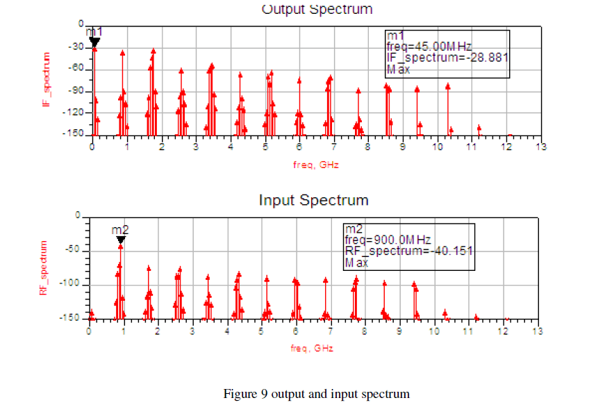
| Figure 9 shows the input and output spectrum of proposed Gilbert mixer i.e. IntermediateFrequency Spectrum and Radio Frequency Spectrum. In the input spectrum marker m1 at the highest node of spectrum shows 45MHz output frequency which is desired output of Gilbert mixer, IF_Spectrum of -28.881 max. |
 |
 |
CONCLUSION
|
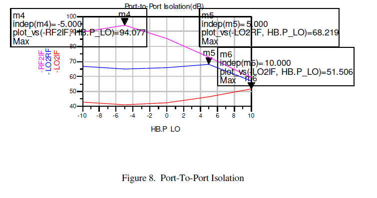
| Theoretical value and simulated value are matched .Gain, port to port isolation and noise figure was improved due to use of Gilbert mixer with inductive source degeneration for GSM applications .Also we can obtain the different values of RF for different applications. |
References
|
- M. Terrovitis and R. Meyer, " Noise in current-commutating CMOS mixers,"Solid-State Circuits, IEEE Journal of, vol. 34, no. 6, pp. 772 - 783, Jun 1999.
- T. H. Lee, The Design of CMOS Radio-Frequency Integrated Circuits, Second Edition. Cambridge University Press, 2004.
- J.-J. Hung, T. M. Hancock, and G. M. Rebeiz, \A 77 GHz SiGe Sub-HarmonicBalanced Mixer," IEEE Journal of Solid-State Circuits, vol. 40, pp. 2167-2173,November 2005.
- M. Terrovitis and R. Meyer, " Noise in current-commutating CMOS mixers,"Solid-State Circuits, IEEE Journal of, vol. 34, no. 6, pp. 772 - 783, Jun 1999
- Cotter W. Sayre “Complete Wireless Design” ,Second Edition, 0-07-164272-2, PP392,395 Press 2008.
- Eldek, A. A., A. Z. Elsherbeni, and C. E. Smith, “Rectangular slot antenna with patch stub for ultra wideband applications and phased arraysystems,” Progress In Electromagnetics Research, PIER 53,227–237, 2005 T. Lee, H. Samavati, and H. Rategh, "5-Ghz CMOS wireless LANs," Microwave Theory and Techniques, IEEE Transactions on, vol. 50, no. 1, pp. 268 -280, Jan 2002.
- http://www.msm.ele.tue.nl/~jvdtang/homepage
- http://www.agilent.com/homepage find/eesof BSIM3 Model (BSIM3 MOSFET Model) - ADS 2008 - Agilent EEsof Knowledge Center.htm
- “Mini Circuits”, AN-00-010 Rev.: OR M118120 (06/17/08) File: AN00010.doc. www.google.com
|