ISSN ONLINE(2319-8753)PRINT(2347-6710)
ISSN ONLINE(2319-8753)PRINT(2347-6710)
Selvapriyanka. P1, Vijayakumar. G2
|
| Related article at Pubmed, Scholar Google |
Visit for more related articles at International Journal of Innovative Research in Science, Engineering and Technology
Developments in global policies have seen the push for greater use of renewable energy sources. Particle Swarm Optimization based Maximum Power Point Tracking (MPPT) algorithm for solar panel is proposed. The solar panel is modeled and analyzed in MATLAB/SIMULINK. The Solar panel can produce maximum power at a particular operating point called Maximum Power Point (MPP).To produce maximum power and to get maximum efficiency, the entire photovoltaic panel must operate at this particular point. This proposed method has the ability to track the MPP for the extreme environmental condition, e.g., large fluctuations of insolation and partial shading condition. The algorithm is simple and can be computed very rapidly. To optimize the utilization of large arrays of photovoltaic modules, maximum power point tracker (MPPT) is normally employed in conjunction with the power converter (dc–dc converter and/or inverter). However, due to the varying environmental condition, namely temperature and solar insolation, the power– voltage characteristic curve exhibits a maximum power point (MPP) that varies nonlinearly with these conditions—thus posing a challenge for the tracking algorithm.
Keywords |
| Maximum Power Point Tracking, Partial Shading, Particle Swarm Optimization, Photovoltaic System. |
INTRODUCTION |
| The increasing world’s energy demands and environmental pollution are motivating research and technological investments related to renewable energy sources. Among various renewable energy systems, PV power generation systems are expected to play an important role as a clean power electricity source since solar energy offer to install easily to the end of users in roof-tops of residence and facades of buildings. It is crucial to improve its efficiency and develop reliability of PV generation control systems. In practical applications, a PV module consists of many solar cells which are connected in series and PV modules are wired together into array both in series and in parallel to provide the necessary voltage or currents. The output power of a PV array decreases considerably, when current-voltage (I–V) curves of solar cells are not identical due to soiling, non uniform irradiation, cloud, cell damaging, partially shading etc (Bangyin 2009). Several MPPT algorithms have been reported in the literature. The most common algorithm is perturb and observe (P&O) method. This control strategy requires external circuitry to repeatedly perturb the array voltage and subsequently measure the resulting change in the output power. While P&O is inexpensive and relatively simple, the algorithm is inefficient in the steady state because it forces the system to oscillate around the MPP instead of continually tracking it. Furthermore, the P&O algorithm fails under rapidly changing environmental conditions, because it cannot discern the difference between changes in power due to environmental effects versus changes in power due to the inherent perturbation of the algorithm. The incremental conductance (INC) method uses the fact that the derivative of the array power with respect to the array voltage is ideally zero at the MPP, positive to the left of the MPP, and negative to the right of the MPP. The INC method has been shown to perform well under rapidly changing environmental conditions, but at the expense of increased response times due to complex hardware and software requirements. The Fractional Open Circuit Voltage (FOCV) method uses an approximate relationship between VOC, the open circuit voltage of the array, and VM, the array voltage at which maximum power is obtained, to track the MPP. Like P&O, the FOCV algorithm is inexpensive and can be implemented in a fairly straight-forward manner. However, the FOCV method is not a true MPP tracker since the assumed relationship between VOC and VM is only an approximation. Fuzzy logic and neural network-based algorithms have demonstrated fast convergence and high performance under varying environmental conditions, but the implementation of these algorithms can be undesirably complex (Alajmi 2011). To this end, a general problem associated with MPPT algorithms is the transient oscillations in the system output voltage after the duty cycle is rapidly changed in order to track the MPP. Thus, the ideal MPPT control algorithm would be simple and inexpensive, and would demonstrate rapid convergence to the MPP with minimal oscillation in the output voltage. |
II. EQUIVALENT CIRCUIT OF A SOLAR CELL |
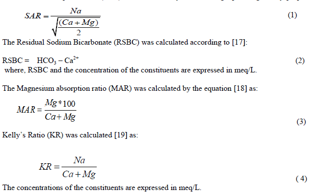
| The equivalent circuit of the general model which consists of a photo current, a diode, a parallel resistor expressing a leakage current, and a series resistor describing an internal resistance to the current flow is shown in Fig. 1. I-V characteristic equation of a solar cell is shown in equation 1 (Ishaque 2011). |
 |
 |
 |
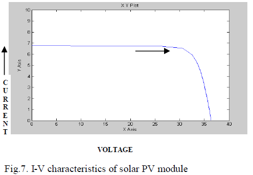
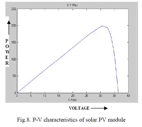
| The I-V characteristics of a typical solar cell are as shown in the Fig. 2. When the voltage and the current characteristics are multiplied we get the P-V characteristics as shown in Fig. 3. The point indicated as MPP is the point at which the panel power output is maximum. |
 |
III. CONVENTIONAL PERTURB & OBSERVE METHOD |
| The Perturb & Observe algorithm states that when the operating voltage of the PV panel is perturbed by a small increment, if the resulting change in power ΔP is positive, then we are going in the direction of MPP and we keep on perturbing in the same direction (Femina 2005). If ΔP is negative, we are going away from the direction of MPP and the sign of perturbation supplied has to be changed. |
| Fig. 4 shows the plot of module output power versus module voltage for a solar panel at a given irradiation. The point marked as MPP is the Maximum Power Point, the theoretical maximum output obtainable from the PV panel. Consider A and B as two operating points. |
 |
| As shown in the Fig. 4 above, the point A is on the left hand side of the MPP. Therefore, we can move towards the MPP by providing a positive perturbation to the voltage. On the other hand, point B is on the right hand side of the MPP. When we give a positive perturbation, the value of ΔP becomes negative, thus it is imperative to change the direction of perturbation to achieve MPP. However, in this algorithm we use only one sensor, that is the voltage sensor, to sense the PV array voltage and so the cost of implementation is less and hence easy to implement. The time complexity of this algorithm is very less but on reaching very close to the MPP it doesn’t stop at the MPP and keeps on perturbing in both the directions. When this happens the algorithm has reached very close to the MPP and we can set an appropriate error limit or can use a wait function which ends up increasing the time complexity of the algorithm. |
| Despite the simplicity of the algorithm, the performance of P&O method is heavily dependent on the tradeoff between the tracking speed and the oscillations that occurs around the MPP. A small perturbation reduces the oscillations but at the expense of tracking speed, or vice versa. Another major drawback of P&O is that during rapid fluctuations of insolation, the algorithm is very likely to lose its direction while tracking the true MPP. Moreover, under special condition such as partial shading and modules irregularities, these methods often fail to track the true MPP because the PV curves are characterized by multiple peaks (several local and one global). Since the P&O algorithm could not distinguish the correct peak, its usefulness under such conditions diminishes rapidly. |
IV. PROPOSED METHOD |
| In this paper, particle swarm optimization method is proposed. The P&O method is eliminated due to its slow convergence speed. Perturbation done based on the concept of particle swarm optimization. The flowchart of the proposed MPPT scheme is shown in the Fig. 5. In this scheme Particle Swarm Optimization with MPPT Controller is used to find out the maximum power point. |
A. PSO-Based MPPT for PV Systems |
| PSO was introduced by James Kennedy and Russell C Eberhart in the year 1995. PSO is a stochastic, population-based EA search method, modeled after the behavior of bird flocks. The PSO algorithm maintains a swarm of individuals (called particles), where each particle represents a candidate solution. Particles follow a simple behavior: emulate the success of neighboring particles and its own achieved successes. The position of a particle is, therefore, influenced by the best particle in a neighborhood P best as well as the best solution found by all the particles in the entire population G best . The particle position xi is adjusted using |
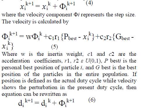 |
| However, for the case of PSO, resulting perturbation in the present duty cycle depends on Pbest and Gbest. If the present duty cycle is far from these two duty cycles, the resulting change in the duty cycle will also be large, and vice versa. In the latter, the perturbation in the duty cycle is always fixed but in PSO it varies according to the position of the particles. With proper choice of control parameters, a suitable MPPT controller using PSO can be easily designed. |
 |
| The following figure illustrates the flowchart of the PSO method, |
| i). Equation (4) shows that the perturbation in duty cycle is computed by two difference terms: the difference between the previous duty cycle di (k) and the local best particles Pbesti , and the difference between the previous duty cycle di (k) and the global best particle Gbest . Thus, the power converter tracks the two best Pbesti and Gbest at the same time. As a result, the tracking spaces are searched to obtain an optimal solution with a faster speed. |
| ii). Once the particle reaches MPP, the velocity of particles is practically zero. Hence, at steady state no oscillations will be seen. These steady-state oscillation are very critical because it is one of the major reasons for the reduced MPPT efficiency. |
| iii). In the case of rapid fluctuations in the environmental conditions, the P&O method can lose the direction of new MPP and tracking could be driven into a wrong direction. However, the proposed method works on three duty cycles. Since the operating power information is obtained from all three duty cycles, it never loses the direction of MPP—in rapid fluctuations. |
| iv). In the condition of partial shading, the P−V characteristic curve is characterized by multiple peaks. As a result, the HC method is most likely to trap at local axima. On the other hand, the PSO method works based on a searching scheme. Hence, it can still track the global peak correctly. |
V. SIMULATION MODEL AND RESULTS |
| The diagram of the proposed method designed in MATLAB and Simulink is shown in Figure 6, which includes the PV module, the buck-boost converter (Rashid, 2004) and the MPPT algorithm. The buck–boost dc/dc converter is utilized due to several reasons, namely it exhibits superior characteristics with respect to the performance of PV array’s MPP and it follows the MPP at all times, regardless of the solar insolation, the array temperature, and the connected load. The PV module current and voltage are fed to the converter and the MPPT controller simultaneously. |
 |
| To test the system operation, the condition of changing solar insolation was modeled. The temperature is constant at 25 oC and irradiance of about 0.9 is shown in Fig. 6. I-V and P-V characteristics curve are shown in Fig. 7 and Fig. 8. |
 |
 |
| The problem considered by P&O based MPPT techniques is to automatically find the voltage VMPP or current IMPP at which a PV array should operate to obtain the maximum power output PMPP under a given temperature and irradiance. |
 |
 |
| Under partial shading conditions, in some cases it is possible to have multiple local maxima, but overall there is still only one true MPP. Most techniques respond to changes in both irradiance and temperature, but some are specifically more useful if temperature is approximately constant. |
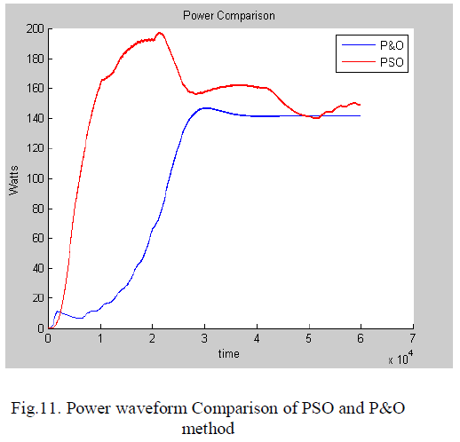 |
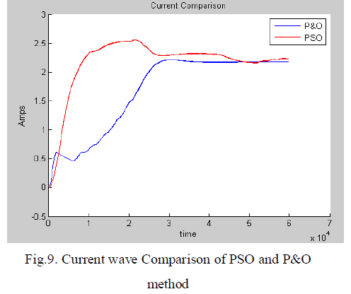
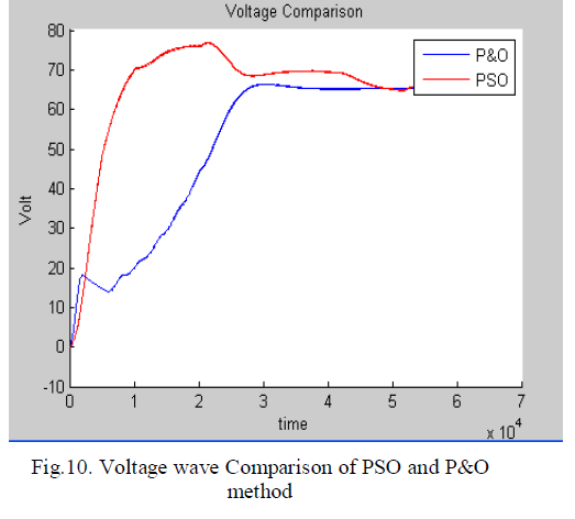
| The proposed PSO optimization output waveform for current, voltage and power is shown in above figures. When the PV array is operating in a uniform solar insolation, the resulting P−V characteristic curve of the array exhibits a single MPP. During partial shading, the P−V curves are characterized by multiple peaks, i.e., with several local and one global peak. |
VI. CONCLUSION |
| This paper evaluates and compares the proposed method with the conventional P&O algorithm based MPPT. The conventional MPPTs are incapable to detect the maximum power point under rapidly changing insolation conditions. Hence these algorithms cannot be employed in PV system to extract maximum available PV power. To improve the tracking speed, a simple and efficient PSO method is used to reinitialize the particles to search for the new MPP, resulting in superior dynamic response. The results indicate that the proposed PSO controller outperforms and gives a number of advantages it has a faster tracking speed, it exhibits zero oscillations at the MPP, it could locate the MPP for any environmental variations including partial shading condition and large fluctuations of insolation and this algorithm can be easily developed. |
References |
|