Keywords
|
| BLDC motor, DTC, PI, PSO, MATLAB/simulink. |
INTRODUCTION
|
| Current researches have been tailored towards developing brushless direct current motors, which are fast becoming alternatives to the conventional dc motor types. The Brushless Direct Current (BLDC) motors are gaining grounds in the industries, especially in the areas of appliances production, aeronautics, medicine, consumer and industrial automations and so on. The BLDC motors are typically permanent magnet synchronous motors that are well driven by dc voltage. Some of the advantages of a brushless dc motor over the conventional brushed dc motors are better speed versus torque characteristics, high dynamic response and high efficiency. Another vital advantage is that the ratio of torque delivered to the size of the motor is higher, and this contributes to its usefulness in terms of space and weight consideration. There are several methods to vary the speed of a BLDC motor over a wide range. Techniques for control of current include vector control, predictive control, dead-beat control, and direct torque control. The most modern technique is direct torque control method (DTC). The DTC offers many advantages like fast torque response, no need of coordinate transformation and less dependence on the rotor parameters. The conventional PI (proportional, integral) control method is widely used in motor control system due to the simple control structure and easiness of design. However tuning the parameters of PI controller is a difficult task. To enhance the capabilities of traditional PI parameter tuning techniques, several intelligent approaches have been suggested such as genetic algorithms (GA) and the particle swarm optimization (PSO). |
| Particle Swarm Optimization is one of the modern algorithms used to solve global optimization problems. Thus, to solve an optimization problem, PSO applies a simplified social model. Compared to other methods, application of the PSO is simple to implement, it can quickly find a number of high quality solutions, and has stable convergence characteristics. The PSO method is an excellent optimization methodology and a promising approach for solving the optimal PI controller parameters problem. |
Purpose of the present work:
|
| The objective of the present work is to provide an alternative approach to improve the speed performance of BLDCM drive. This method uses the principle of Direct Torque Control, which is based both on field oriented control (FOC) as well as on the direct self-control theory. DTC offers direct control of stator flux and electrical torque there by reducing the speed error resulting in better speed control of BLDC drive. In this project one of the modern algorithms called particle swarm optimization technique is used to reduce the speed error of BLDC motor, hence overcoming the major drawbacks of conventional methods. |
MATHEMATICAL MODELING OF BLDC MOTOR
|
| Typically, the mathematical model of a brushless DC motor is not totally different from the conventional DC motor. The major difference is the phases involved in the operation of BLDC motor drive will peculiarly affect the resistive and the inductive nature of the BLDC model arrangement. The mathematical model of the BLDC motor is modelled based on the equations illustrated below: |
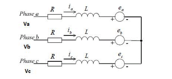
Fig 1:Electrical equivalent circuit of BLDC motor |
| The coupled equations of the stator windings in terms of motor electrical constants are |
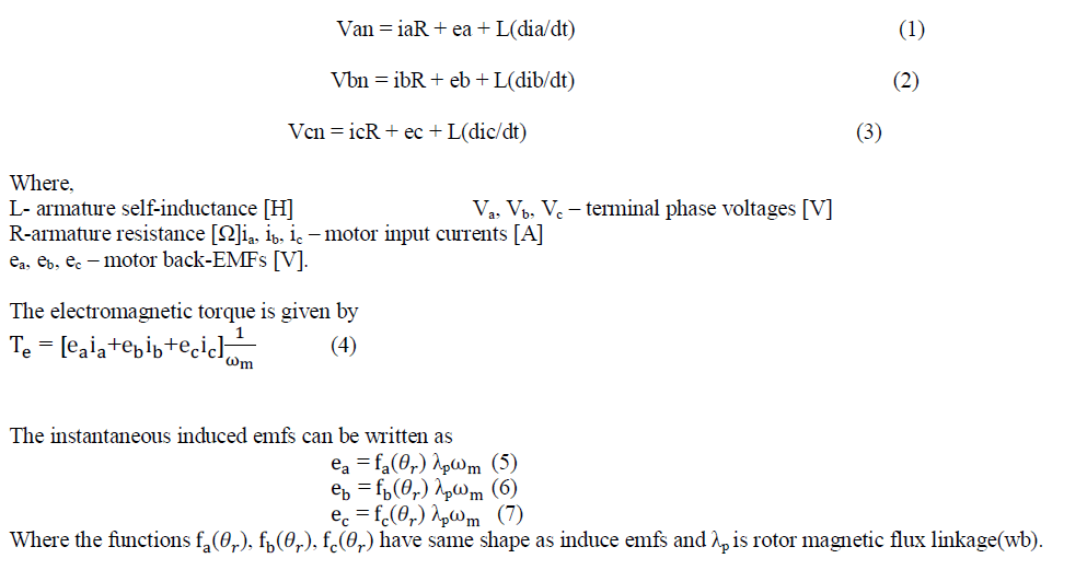 |
| The equation of motion for a simple system with inertia J , friction coefficient B, and load torque T1 is |
 |
DIRECT TORQUE CONTROL OF BLDC MOTOR
|
| DTC strategies have been widely implemented in induction machine drives. They allow a direct control of the electromagnetic torque and the stator flux through the application of suitable combinations of the control signals of the inverter switches. Therefore in DTC, Torque is controlled through the selection of optimal inverter switching states. DTC technique is superior to vector control because of the advantages like fast torque response, low inverter switching frequency, low harmonic loss, absence of coordinate transformation. This control strategy in this paper has been applied for BLDC drive |
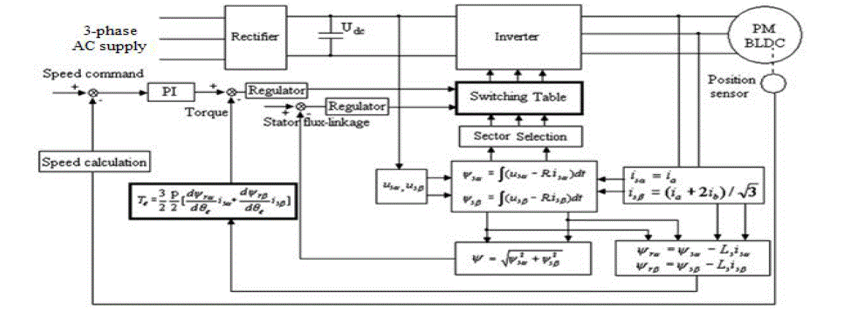
Fig 2:Block diagram of direct torque control of BLDC motor |
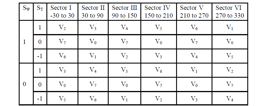
| The basic control algorithm of DTCconsists of two independent hysteresis comparators producing the error signal of stator flux and electrical torque.A two-level hysteresis flux comparator and a three level hysteresis torque comparator compare the actual values to the reference values produced by flux and torque reference controllers. Depending on the outputs from the two hysteresis controllers, the optimum switching logic selects one of the six voltage vectors and two zero voltage vectors generated by a VSI in order to keep stator flux and torque within the limits of two hysteresis bands.The angle of the stator flux vector is used to determine the voltage sector as shown on the Fig.3 |
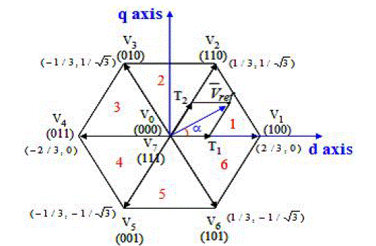
Fig.3 Voltage vector diagram |
| Six nonzero vectors (V1 – V6) shape the axes of a hexagonal as depicted in the above figure and feed electric power to the load. The angle between any adjacent two non-zero vectors is 60 degrees. Meanwhile, two zero vectors (V0 and V7) are at the origin and apply zero voltage to the load. The eight vectors are called the basic space vectors and are denoted by V0, V1, V2, V3, V5, V6, and V7. Assuming the stator flux vector laid on the sector 1 of the d-q plane, V1, V2, V6 could be selected to increase the stator flux vectors. Conversely, V3, V4, V5 could be selected to decrease the stator flux vector. The zero (null) voltage vectors does not effect on the stator flux vector. Voltage vectors are selected to control the torque also. In general, V2 and V3 vectors can be selected to increase the torque and V5 and V6, vectors willdecrease the torque. Table 1 shows voltage vector selection according to stator flux and torque errors. |
Table1:Switching voltage vectors
 |
PARTICLE SWARM OPTIMIZATION
|
| Particle swarm optimization is a heuristic global optimization method put forward originally by Doctor Kennedy and Eberhart in 1995. It is developed from swarm intelligence and is based on the research of bird and fish flock movement behaviour. PSO has two primary operators; velocity and position update. In this paper the main objective of PSO is minimization of speed error. Fig.4 shows the block diagram for PI controller and the corresponding objective function is as shown in equation (9) and (10). |
| ωrefTe * |

Fig.4. PI controller |
 |
PSO algorithm:
|
Step.1 initialization
|
| Determine the particle size m and set the values of parameters c1 and c2. Initialize weight factor w. Randomly generate the particles to be the candidate solutions to the optimization problem called population vector. The size of Population vector (pv)=[kpki]mx2. i.Where m=particle size. Population vector (PV) is generated by using the formula a.PV=kpmin+ (rand (m, 1)*(kpmax-kpmin). Substitute this data in objective function to obtain fitness vector. Fitness vector= [ ]mx1. |
Step.2 velocity vector calculation v(t)
|
| In the original version of PSO, each component of velocity vector is kept within the range [−Vmax,Vmax]. Vmax= (kpmax- kpmin)/n; Where n=number of iterations. Order of velocity vector=ps x ncv. Where ps=particle size, ncv=number of control variables. |
Step.3 Calculation of pbest and gbest
|
| pbestpopulation = population vector(pv). pbestfitness = fitness vector(fv). Gbest is the best position among all individual best positions achieved so far. |
Step.4 Iteration process
|
| Weight updating |
| W(t)=alpha*w(t-1). |
| Where alpha= random number. |
| Velocity updating |
| V(t)=w(t)*v(t-1)+c1*r1*(pbest-xi)+c2*r2(gbest-xi). |
| Where xi=current location. |
| Position updating |
| Xik+1 =v(t)+xik |
| Where Xik+1 =new position. |
| Xik =previous location. |
Step.5 Stopping criteria
|
| The objective function (fitness) value is calculated for each agent according to above steps, that is Epbest.Compare particle’s fitness evaluation (Epbest) with its Gbest. If current value is better than Gbest then set Gbest equal to the current value and that position equal to the current location xi in D-dimensional space. |
Step.6 Exit condition
|
| If Epbest<error, |
| (or) |
| the number of iterations reaches the maximum allowable number. |
| If one of the above conditions is satisfied then stop. Else go to step 4. The optimal values of kp and ki are substituted in the conventional DTC and the results are obtained. |
RESULT AND DISCUSSION
|
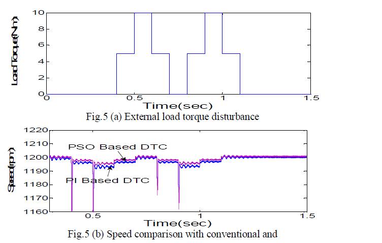
| The optimized values obtained from PSO program are substituted in DTC system and the results have observed. To validate the performance of PSO based DTC different load torques has been applied as shown in fig 5(a), 6(a), 7(a), and 8(a). The motor speed waveforms related to the PSO based DTC in comparison with conventional PI based DTC are as shown in fig 5(b), 6(b), 7(b), 8(b). |
 |
| PSO based DTC |
| In the fig 5(b), it shows the plot of time Vs speed for a load disturbance applied to DTC of BLDC drive in fig.5 (a), by comparing the speed behaviour of conventional PI based DTC with PSO based DTC of BLDC motor, there is less ripple in speed and results in better steady state response of the PSO based DTC. |
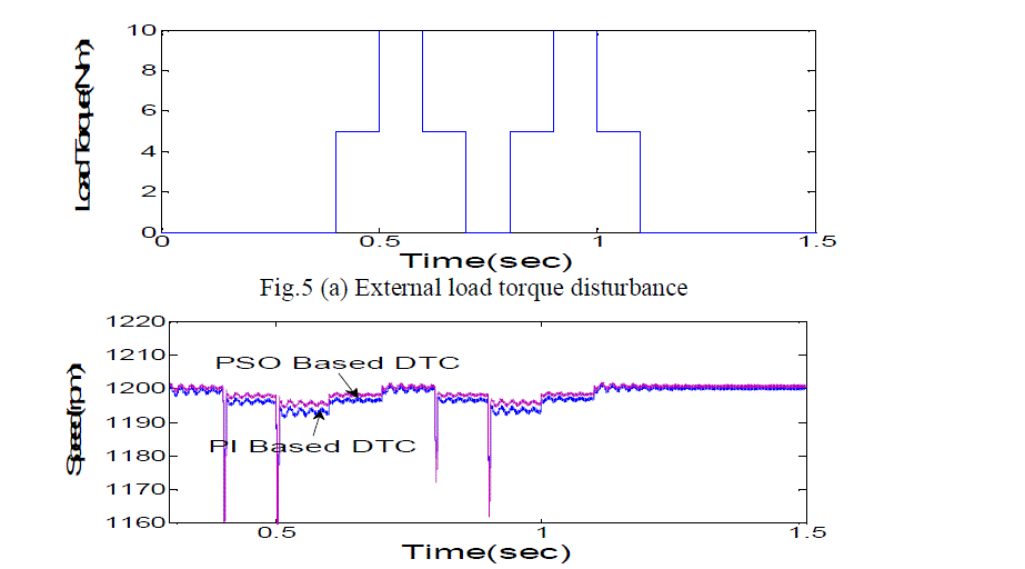
Fig.6 (b) Speed comparison with conventional and PSO based DTC |
| In the fig 6(b), it shows the plot of time Vs speed for a load disturbance applied to DTC of BLDC drive in fig.6(a), by comparing the speed behaviour of conventional PI based DTC with PSO based DTC of BLDC motor, there is less ripple in speed and results in better steady state response of the PSO based DTC. |
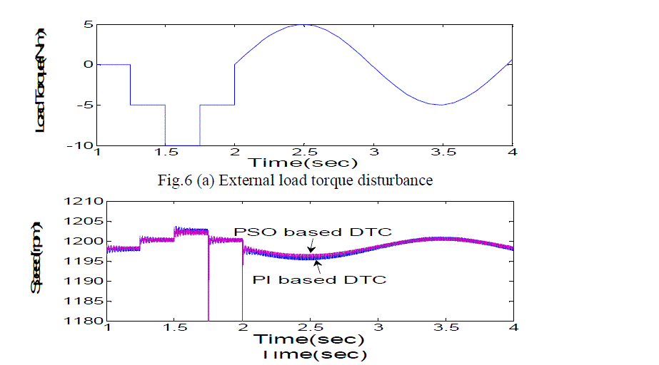
Fig.7 (b) Speed comparison with conventional and PSO based DTC |
In the fig 7(b), it shows the plot of time Vs speed for a load disturbance applied to DTC of BLDC drive in fig.7(a), by comparing the speed behaviour of conventional PI based DTC with PSO based DTC of BLDC motor, there is less ripple in speed and results in better steady state response of the PSO based DTC. |
| It has been observed that the speed performance of a PSO based DTC is better when compared with the conventional DTC. |
CONCLUSION
|
| In this paper, the proposed PSO based DTC of BLDC drive control scheme has been implemented. The simulation results of this method have improved the speed performance of the BLDC motor irrespective of the load torque fluctuations. The PSO method has optimized the parameters of PI controller by minimizing the speed error. It can be concluded that the PSO algorithm employed in DTC of BLDC motor has resulted in the optimal generation of kp, ki values. This method has finally improved the dynamic speed behaviour of the BLDC motor when compared with that of a Conventional PI controller based DTC of BLDC motor. |
References
|
- S. B. Ozturk, W. C. Alexander, and H. A. Toliyat, “Direct torque control of four-switch brushless DC motor with non-sinusoidal back EMF”,IEEE Trans. Power Electron., vol. 25, no. 2, pp. 263-271, 2010.
- F. Jiancheng, L. Haitao, and H. Bangcheng, “Torque ripple reduction in BLDC torque motor with non-ideal back EMF”, IEEE Trans. PowerElectron., vol. 27, no. 11, pp. 4630-4637, 2012.
- Z. Q. Zhu, and J. H. Leong, “Analysis and mitigation of torsional vibration of PM brushless AC/DC drives with direct torquecontroller”,IEEETrans. Ind. Appl., vol. 48, no. 4, pp. 1296-1306, 2012.
- S. B. Ozturk, and H. A. Toliyat, “Direct torque and indirect flux control of brushless DC motor”, IEEE Trans. Mechatronics, vol. 16, no. 2, pp351-360, 2011.
- P. J. Sung, W. P. Han, L. H. Man, and F. Harashima, “A new approach for minimum-torque-ripple maximum-effeciency control of BLDCmotor”, IEEE Trans. Ind. Electron., vol. 47, no. 1, pp. 109-114, 2000.
- AhmudIwanSolihin, Lee Fook Tack and MoeyLeapKean. “Tuning of PID controller using particle swarm optimization” (PSO). 2011
- Hassan FarhanRashag, S.P.Koh, Ahmed N. Abdalla, nadia M. L. Tan, K. H. Chong and S. K. Tiong, “ DTC torque ripple minimization based onPSO-PID controller”. Scientific research and Essay., vol. 7,pp(15), 1564-1572, 2012.
- J. Kennedy and R. C. Eberhart, “ Particle Swarm Optimization,” in Proc. IEEE Int. of Neural Networks, Piscataway, NJ, USA, 1942-1948, 1995.
- O.S. EI-Laban , H.A. Abdel Fattah, H.M.Emara, and A.F.Sakr, “partical swarm optimized direct torque control of induction motors”. IEEETrans, 2006
- 1 Eberhart R C, Shi Y. (1998). Comparison between genetic algorithms and Particle Swarm Optimization.PortoVW.SaravananN,Waagen D, etal.Evolutionary Programming VII.S.l.]:Springer,1998:611-616
|