Induction motor plays a vital role in engineering and industry. Induction motor offer a convenient means for controlling the operation of different equipment used in industry. Induction motor input supply will give from the voltage source inverter for its speed control purpose. If we connect induction motor directly to the AC supply its speed control will not applicable, so that we go inverter fed induction motor speed control. Gate pulse has been given by using FPGA processor. Fuzzy flatness program has been flashed in the FPGA processor for generating the gate pulse for VSI inverter. FPGA processor is directly fed to opto-coupler and the driver circuit and then it has given to VSI inverter. Her closed loop control has been achieved by using inductive type proximity sensor. In closed loop control when input voltage has been changed but speed of the induction motor has maintained constant. Fuzzy flatness based control is applied in the speed controller of induction motor. This method gives better efficiency of induction motor speed control. Fuzzy flatness controller method for induction motor gives better performance and reduces tracking error and reduces the torque ripple.
Keywords |
| VSI Inverter, Fuzzy flatness control and Induction motor. |
INTRODUCTION |
| Induction motors are the most frequently used machines in various electrical drives. About 70% of all industrial
loads on a utility are represented by induction motors. The control task is further complicated by the fact that induction
motors are subject to unknown disturbances and the parameters are of great uncertainty. We are faced then with the
challenging problem of controlling a highly nonlinear system, with unknown time-varying parameters, where the regulated
output, besides being unmeasurable is perturbed by an unknown additive signal. The issue of controlling electrical drives is
nowadays widely solved with the so called field oriented control or vector control. However, tracking control of induction
motor [3] the performance will be degraded face to motor parameter variations or unknown external disturbances. To offer
control robustness with minimum complexity, have been proposed to improve the control performance. Some nonlinear
control methods were applied to the speed and flux control of the induction machine. |
| The assumptions of different time constants of the loops or a constant rotor flux are not necessary. Fuzzy logic
controller has been explained [1], [5] and [6]. The flatness property was used to control continuous nonlinear systems with
good performances in term of tracking trajectory. Membership function has been [7], [8] for different function The flatnessbased
approach described in [2] uses the characterization of system dynamics to generate a suitable output. The flatness
control in an induction motor is an important subject because of the need for improvement in operation quality. It, however,
is a difficult problem for a conventional approach to achieve since the induction motor driving process is a highly nonlinear
system in which many uncertain parameters are involved. Fuzzy control has adaptive capacity to time lag, nonlinearity and
uncertain parameters in controlled system. |
| VSI fed induction motor speed control has explained [10]. A fuzzy controller for the flatness control is designed is
to improve the control performance of the induction motor. Designing a fuzzy controller without using the cascade structure
is possible due to the flatness of the complete machine model. Especially for small inertias this could be a promising
possibility. Further investigations should be done on designing the reference trajectory generation. To exploit the
possibilities the control input limitations should be directly taken into account. |
THREE PHASE INVERTER |
| The function of an inverter is to change a DC input voltage to an AC output voltage of desired frequency and
magnitude. In case of 3-phase inverter, the inverter circuit changes a DC input voltage to a symmetrical AC output voltage
of desired magnitude and frequency. Output voltage could be fixed or variable at a fixed or variable frequency. Variable
output voltages are obtained by varying the input DC voltage with maintaining the gain of the inverter constant.
Meanwhile, if the DC input voltage fixed and not controllable, variable output voltage can be obtained by varying the
frequency of the inverter which is usually done by implementing PWM control within the inverter. |
 |
| The output voltage of an inverter has a periodic waveform which is not purely sinusoidal, but with number of
techniques it can be designed to closely approximate to this desired waveform. Inverter can be built with any number of
output phases. Practically, single-phase and three-phase inverters are most commonly used. It depends on the user
requirement whether in the industrial applications, transportations and home appliances. In most circumstances, three-phase
inverter offered better performances as compared to single-phase inverter. Power semiconductors switches are the basic
building component of the inverter. Generally there were two types of inverter topology, named as Voltage Source Inverter
and Current Source Inverter. Voltage waveform is the independently controlled AC output in the VSI topologies.
Meanwhile, in CSI topologies, the independently controlled AC output is a current waveform. VSI can be further divided
into three categories which are PWM Inverter, Square Wave Inverter and Single-phase Inverters with Voltage Cancellation.
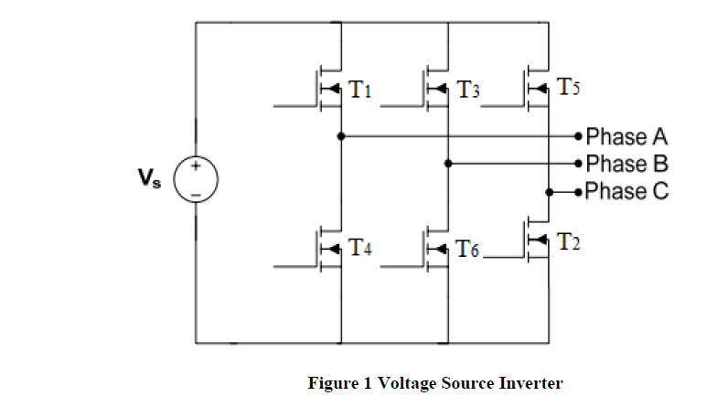
The close-up for 3-phase VSI is shown in Figure 1. The structure of VSI is more widely used in the industrial application
due to the voltage source requirement. |
A. THREE PHASE 120 DEGREE MODE OF OPERATION |
| In the three phases IGBT inverter of each conducts for 120 degree of a cycle. IGBT pair in each arm, T1, T4; T3, T6
and T5, T2 is turned on with a time interval of 120 degree. It means that T1 conducts for 120 degree and T4 for the next 120
degree of a cycle. IGBTs in the upper group, T1, T3, T5 conduct at an interval of 120 degree. It implies that if T1 is fired at
ωt=0 degree. Then T3 must be fired at ωt=120degree and T5 at ωt=240degree. Same is true for lower group of IGBTs. On
the basis of this firing scheme. In this T1 from upper group conducts for 120 degree, T4 for next 120degree and then again
T1 for 120degree and so on. In the second row, T3 from the upper group is shown to start conducting 120degree after T1
start conducting. After T3 conducting for180degree, T6 conducts for the next 180degree and again T3 for the next 180degree
and so on. Further, in the third row, T5 from the upper group starts conducting 120 degree after T3 or 240 degree after T1. |
| After T5 conduction for 120 degree, T2 conducts for the next 120 degree, T5 for the next 120 degree and so on. In
this manner, the pattern for firing the six SCRS is identified. This table shows that T5,T6,T1 should be gated for 1; T6,T1,T2
for step 2.T1,T2,T3 for step 3.T2,T3,T4 for step 4 and so on. Thus the sequence of firing the IGBT is T1, T2, T3.T4.T5 and T6. |
SPEED CONTROLLERS |
| The goal of the controller is to control the speed of induction motor. Conventional and intelligent controllers are
used I voltage control system. It the system having feedback loop, it is fed to the summing point to find out the change in
voltage. The conventional PI controller is mostly used in industries compared to other controller, because the PI controller
has advantages of both proportional and integral controllers. The output power is maintained constant, whereas the
operating voltage is changed. |
| In automatic control systems the reference input will be an input signal proportional to desired output. The
feedback signal proportional to current output of the system. The different types of conventional controllers are P, I PI, PD
and PID controller. The Fuzzy Flatness control in an induction motor is an important subject because of the need for
improvement in operation quality. Flatness based tracking controller is a very important tool for nonlinear controller design.
The flatness property was used to control continuous nonlinear systems with good performances in term of tracking
trajectory. The flatness-based approach uses the characterization of system dynamics to generate a suitable output. |
A. FUZZY FLATNESS CONTROLLER |
| The Fuzzy Flatness control in an induction motor is an important subject because of the need for improvement in
operation quality. Flatness based tracking controller is a very important tool for nonlinear controller design. The flatness
property was used to control continuous nonlinear systems with good performances in term of tracking trajectory. The
flatness-based approach uses the characterization of system dynamics to generate a suitable output. Differential flatness has
proven to be a very powerful concept for analysis and design of open loop and stabilizing feedback tracking control for
nonlinear finite dimensional systems. |
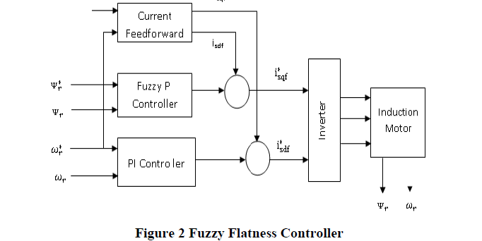 |
| The Figure 2 shows Structure chart of an induction motor with fuzzy flatness controller. Fuzzy Flatness-based
controller for induction motor vector control system. The flatness-based approach uses the characterization of system
dynamics to generate a suitable output and it can control continuous nonlinear systems with good performances in term of
tracking trajectory. Fuzzy logic is used to eliminate the effects of the time-varying nonlinear system. Simulation results
shown that the fuzzy flatness based control scheme can improve the control performance effectively. |
| The property of flatness can effectively be used for designing control algorithms. In general the control structure
consists of a feedforward and a feedback part. Even if the references are smooth enough deviations from perfect tracking
will appear due to disturbances, model uncertainties and other perturbations. Therefore feedback is introduced. Since the
system is near to the reference trajectory via feedforward, thus linearizable around it, the feedback can be designed with
linear methods also for nonlinear systems. Even though the voltage-fed induction machine is flat and the application of
FBC to the complete, nonlinear model would be possible, here a cascade is used due to its simplicity and comparability to
the FOC. |
EXPERIMENTAL SETUP |
 |
 |
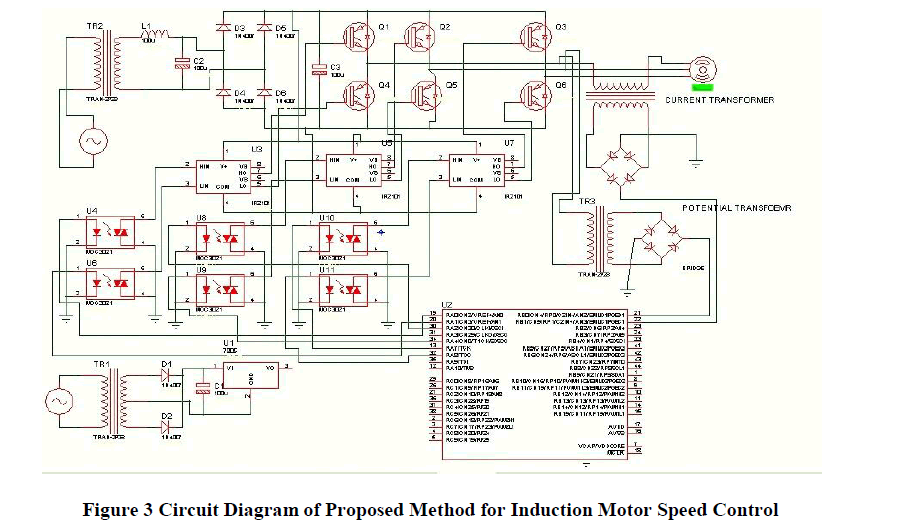
| The Figure 3 shows circuit diagram of Proposed Method for Induction Motor Speed Control. Single phase supply is given
to full wave diode rectifier. The rectified supply is given to VSI inverter for inverter IGBT switch has used. Inverter output
is given to induction motor. For the VSI inverter needs the gate pulse for that FPGA processor and it directly give to gate
drive circuit output is fed to the VSI inverter. . Induction motor closed loop control can achieve by using proximity sensor.
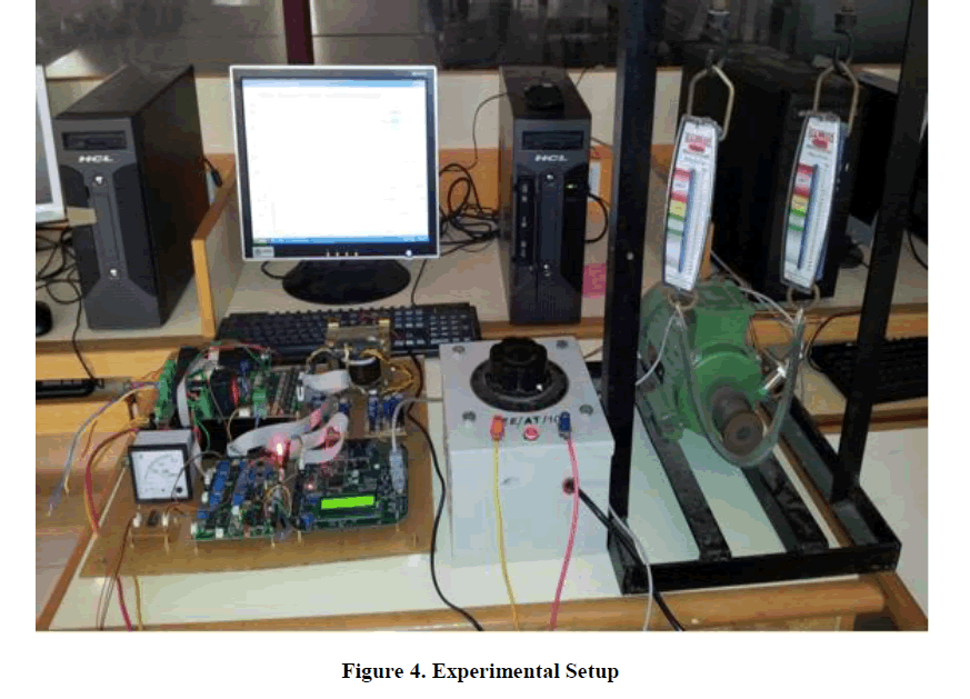
Through RS232 cable speed of the motor monitoring in the system. The Figure 4 shows experimental setup for induction
motor. |
EXPERIMENTAL RESULT AND ANALYSIS |
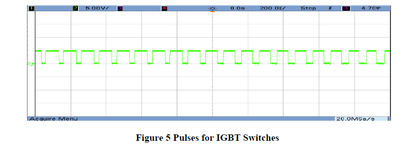
`A. Pulse for IGBT Switches |
| Pulse generation of the voltage source inverter can give by using FPGA processor. The output waveform has been
taken by using DSO (Digital Storage Oscilloscope). Based on the speed variation of the induction motor closed loop control
the pulse can be varied. The Figure 5 shows the input pulse for VSI inverter. |
 |
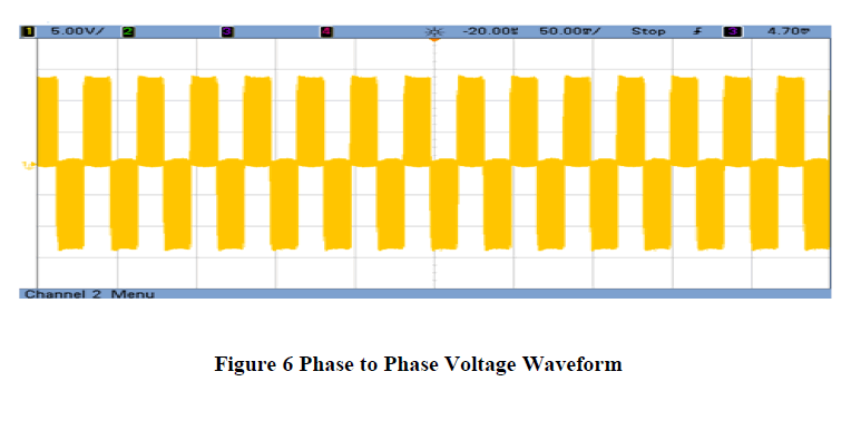
B. Phase to Phase Voltage waveform |
| The Figure 6 shows phase to phase voltage at motor running at rated speed condition. At closed loop control the
induction motor speed is constant any small voltage variation at input side. But output voltage will be maintained constant
in the closed loop control of induction motor. The output waveform has been taken by using DSO (Digital Storage
Oscilloscope). |
 |
C. PERFORMANCE OF FUZZY FLATNESS SPEED CONTROLLER |
| Performance of fuzzy flatness speed controller can be discussed. Steady state performance and transient state
performance result has been discussed. |
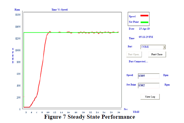
D. Steady State Performance |
| The Figure 7 shows the steady state performance. Speed control from 0 to 1302RPM. Initially speed has been set
as 1302 RPM by using incremental key. |
| After that we can vary the single phase auto-transformer 0Volts to 230Volts at that same time three phase
induction motor speed can vary from 0 to set speed 1302 RPM. Initially motor starts from 4seconds and it rise to attain its
maximum speed 1302 at 10seconds. Total time taken to attain its set speed will be 6seconds. Maximum overshoot will be
2seconds. Speed curve between set speed and its actual speed of the induction motor has been shown and also set speed and
actual speed value will be displayed. The curve shows the set speed (vs) actual speed of three phase induction motor. By
using RS232 cable communication hardware to system has been interfaced. The output speed waveform can be monitoring
in the system. By using VB software coding speed monitoring system has been developed. |
 |
| After that we can vary the single phase auto-transformer 0Volts to 230Volts at that same time three phase
induction motor speed can vary from 0 to set speed 1302 RPM. Initially motor starts from 4seconds and it rise to attain its
maximum speed 1302 at 10seconds. Total time taken to attain its set speed will be 6seconds. Maximum overshoot will be
2seconds. Speed curve between set speed and its actual speed of the induction motor has been shown and also set speed and
actual speed value will be displayed. The curve shows the set speed (vs) actual speed of three phase induction motor. By
using RS232 cable communication hardware to system has been interfaced. The output speed waveform can be monitoring
in the system. By using VB software coding speed monitoring system has been developed. |
E. Transient State Performance |
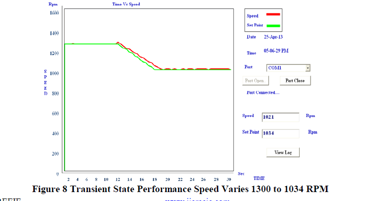 |
| The Figure 8 shows the transient state performance speed varies 1300 to 1034 RPM. Induction motor running at
1300 RPM then by using decrement key set speed as 1034 RPM. Single phase auto-transformer constant 230Volts at that
same time three phase induction motor speed can vary from 1300 RPM to set speed 1034 RPM. Set speed has been tracked
and its actual speed can be varied. Initially induction motor speed 1300 RPM and it reaches 1034 RPM within 7seconds.
Speed curve between set speed and its actual speed of the induction motor has been shown and also set speed and actual
speed value will be displayed. The curve shows the set speed vs actual speed of three phase induction motor. |
| The Figure 9 shows the speed control waveform 1000 to 1310 RPM. Induction motor running at 1000 RPM then
by using incremental key set speed as 1310 RPM. |
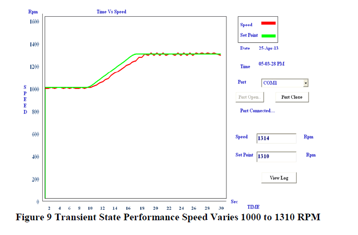 |
| Single phase auto-transformer constant 230Volts at that same time three phase induction motor speed can vary
from 1000RPM to set speed 1310RPM. . Set speed has been tracked and its actual speed can be varied. Initially induction
motor speed 1000 RPM and it speed has been decreased 1310 RPM within 8seconds. Time taken to attain set speed will be
very few seconds only. Speed curve between set speed and its actual speed of the induction motor has been shown and also
set speed and actual speed value will be displayed. The curve shows the set speed vs actual speed of three phase induction
motor |
CONCLUSION |
| Fuzzy Flatness based tracking controller is a very important tool for nonlinear controller design. The Fuzzy
Flatness property was used to control continuous nonlinear systems with good performances in term of tracking trajectory.
The flatness-based approach uses the characterization of system dynamics to generate a suitable output. The flatness
control in an induction motor is an important subject because of the need for improvement in operation quality. It, however,
is a difficult problem for a conventional approach to achieve since the induction motor driving process is a highly nonlinear
system in which many uncertain parameters are involved. Fuzzy control has adaptive capacity to time lag, nonlinearity and
uncertain parameters in controlled system Fuzzy logic based flatness control can improve the operation performance of the
induction motor effectively. The performance of fuzzy flatness controller for the speed control voltage source inverter fed
induction motor drive has been verified and compared with that of conventional PI controller performance. By applying
fuzzy flatness control we can reduce the tracking error and torque ripple of the induction motor. This provides a better
method for controlling induction motor. |
References |
- Arulmozhiyal, and Dr. Baskaran K “Speed Control of Induction Motor using Fuzzy PI and Optimized using GA” International Journal ofRecent Trends in Engineering, Vol.2, No.5, pp.43-47 Feb.2009.
- AzeddineHouari, HuguesRenaudineau, Jean-Philippe Martin, Serge Pierfederici, and FaridMeibody-Tabar, “Flatness-Based Control ofThree-Phase Inverter with Output LC Filter” IEEE Transactions on Industrial Electronics, Vol.59, No.7, pp.2890-2897 Dec.2012
- Chao-Lung Chianga, Ching-Tzong , “Tracking Control of Induction Motor Using Fuzzy Phase Plane Controller with Improved GeneticAlgorithm” Department of Electrical Engineering, Elsevier Journal on Power System Engineering Research, Vol.73, No.5, pp. 239-247April.2005
- Durgasukumar, M.K.Pathak , “Torque Ripple Reduction in VSI Fed Induction Motor Drive Using Low Switching Frequency” InternationalJournal of Engineering Science and Technology Vol. 2, No.10, pp.6113-6119 May.2010
- Durval de Almeida Souza, Wilson C. P. de AragãoFilho, and Gilberto Costa Drumond Sousa “Adaptive Fuzzy Controller for EfficiencyOptimization of Induction Motors” IEEE Transactions on Industrial Electronics, Vol. 54, No. 4, pp.2157-2164 June.2007
- Francesco Cupertino, AnnamariaLattanzi, and Luigi Salvatore , “A New Fuzzy Logic-Based Controller Design Method for DC and ACImpressed-Voltage Drives”IEEE Transactions on Power Electronics, Vol. 15, No. 6, pp.974-982 April.2000
- Jaime Fonseca, Joao L. Afonso, Julio S. Martins, Carlos Couto , “Fuzzy Logic Speed Control of an Induction Motor” Elsevier, Vol 27, No.2,pp. 523-534 August.1999
- P.Tripura and Y.Srinivasa Kishore Babu , “Fuzzy Logic Speed Control of Three Phase Induction Motor Drive” World Academy of Science,Engineering and Technology, Vol.60, No.3, pp.1371-1375 Nov.2011
- Praveen Kumar, D.Sunitha , “Speed Control of Induction Motor using PID and Fuzzy Controller” Proceedings of International Conference onComputing and Control Engineering (ICCCE 2012), Coimbatore Institute of Information Technology, Coimbatore, pp.371-375 July.2012
- V.Singh, Y.P. Singh , “Voltage Source Inverter Driven Multi-phase Induction Machine” science direct, Vol.29, No.4, pp.813-834 March.2003
|