Keywords
|
| Fuzzy PID controller, MATLAB, Simulink. |
INTRODUCTION
|
| Fuzzy logic control is most winning applications of fuzzy set theory, introduced by L.A Zadeh in 1970’S and applied Mamdani in an attempt to control system that are structurally tricky to model. Since then, FLC has been tremendously active and fruitful research area with many industrial applications account. FLC has developed as a substitute or complementary to the conventional control policy in various manufacturing areas. Fuzzy control hypothesis usually endow with non-linear controllers that are accomplished of performing different complex non-linear control action, even for uncertain nonlinear systems. Imitating the way of human learning, the tracking error and the rate of the error are two crucial inputs for the design of such a fuzzy control system. |
| In spite of follow a line of investigation and the huge number of altered solutions anticipated, most industrial control systems are base on conventional PID regulators. Different sources estimate the share taken by PID controllers is between 90% and 99%. Some of the reasons for the situation more than 90% share taken by it are as follows [1]: |
| 1. PID controllers are robust and simple to design. |
| 2. There exists a clear relationship between PID and system response parameters. As a PID controller has only three parameters, plant operators have a deep knowledge about the influence of these parameters and the specified response characteristics on each other. |
| 3. Many PID tuning techniques have been elaborated during recent decades, which facilities the operator's task. |
| 4. Because of its flexibility, PID control could benefit from the advances in technology. This paper proposes a design strategy, which makes use of known PID design techniques, before implementing the fuzzy controller: |
| 1. Tune a PID controller |
| 2. Replace it with an equivalent linear fuzzy controller |
| 3. Make the fuzzy controller nonlinear |
| Fuzzy controllers are inherently nonlinear controllers, and therefore fuzzy control technology viewed as a new, cost effective and realistic way of developing nonlinear controllers. The major advantage of this technology over the traditional control technology is its capability of take into custody and utilizes qualitative human experience and knowledge in a quantitative manner through the use of fuzzy sets, fuzzy rules and fuzzy logic. However, carrying out analytical analysis and design of fuzzy control systems is difficult not only because the explicit structure of fuzzy controllers is generally unknown, but also due to their inherent nonlinear and time-varying nature. |
| In this paper, Fuzzy PID controller that uses the simplified linear Mamdani scheme and show through computer simulation on MATLAB/ SIMULINK. The idea is to start with a conventional PID controller, replace it with an equivalent linear fuzzy controller, formulate the fuzzy controller nonlinear and eventually fine-tune the nonlinear fuzzy controller. This is relevant when a PID controller is possible or already implemented. |
MATHEMATICAL MODEL
|
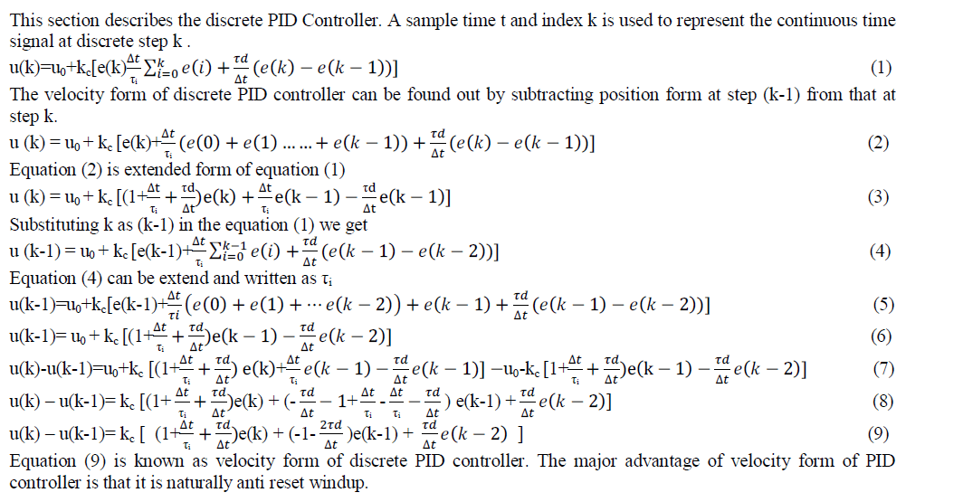 |
FUZZY CONTROLLER
|
| Notions are very modest. They reside of three foremost stages as shown in Figure 2, an input stage, a processing stage, and an output stage. |
| The input stage maps sensor or other inputs, such as switches to the appropriate membership functions and truth values. The processing stage enables each rule and generates a result for each, then combines the results of the rules. Finally, the output stage converts the combined result back into a specific control output value. |
 |
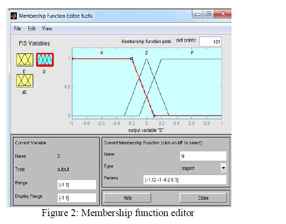
| As discussed previously, the most common shapes of membership functions used are triangular, trapezoidal, Gaussian and bell curves, but the shape is generally less important than the number of curves and their placement. The major components to strategy the fuzzy logic control are Fuzzification, knowledge base, decision making logic and Defuzzification |
MAMDANI METHODE
|
| This method was suggested as an attempt to control a steam engine and boiler combination by synthesizing a set of linguistic control rules achieved from experienced human operators. The source of knowledge of fuzzy logic to construct the control algorithm comes from the control protocol of the human operator. This protocol reside of a set of conditional (If-Then) statements, where the first part of each contains a so-called condition (antecedent)while the second (consequent) part deals with an action (control) that has to be taken. Therefore, it mimics the human strategy which control is to be realized when a certain state of the process controlled is observed. IF(a set of conditions are satisfied) THEN(a set of consequences can be inferred). In classical (crisp) logic, a proposition P is either true or false. In fuzzy logic, a proposition P is assigned a degree of truth or falsity (P can be any value on the interval [0, 1]) with the fuzzy set involved. A fuzzy logic proposition, P, it can be expressed as “IF x is A THEN y is B,” implying that P induces a possibility distribution of y given x. Basically, fuzzy control rules be responsible for a convenient way for expressing control policy and do foremost knowledge and have the form (Mamdani): |
| R1: if x is A1, … and y is B1 then z is C1 |
| R2: if x is A2, … and y is B2 then z is C2 |
| Rn: if x is An, … and y is Bn then z is Cn |
 |
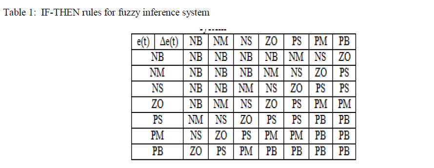
| In below table IF-THEN rules for fuzzy inference system is described. |
 |
SIMULINK MODEL OF FUZZY PID CONTROLLER
|
| By using MATLAB/SIMULINK simulation model is constructed as shown in figure 3 below: |
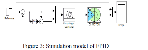 |
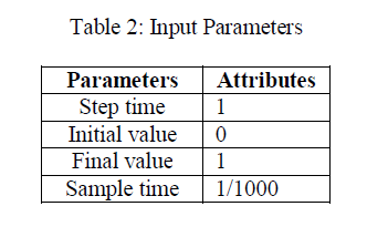
| The very first block is reference or step i.e., input parameters are set as shown in table below: |
 |
| Unit Delay: sample and hold with one sample period delay. |
| Sum: Add or subtract inputs. Specify one of the following: |
| ïÃâ÷ String containing + or - for each input port, | for spacer between ports (e.g. ++|-|++) |
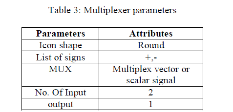
| ïÃâ÷ Scalar, >= 1, specifies the number of input ports to be summed. MUX: many input and give one output, parameters are depend on designer. Here we use following parameter as shown in Table 2 |
 |
| Fuzzy logic controller: Fuzzy Membership function editor, where the number of membership functions and type of membership function is decided. |
5 steps to generate fuzzy rules from numerical data:
|
| • Divide the input and output spaces of the given numerical data into fuzzy regions. |
| • Generate fuzzy rules fro |
| • m the given data. |
| • Assign a degree of each of the generated rules for the purpose of resolving conflicts among the generated rules. |
| • Create a combined fuzzy rule base based on both the generated rules and linguistic rules of human experts. |
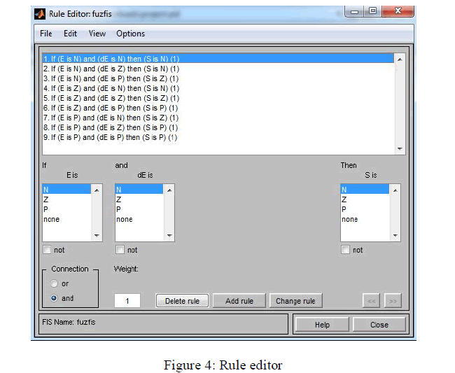
| • Determine a mapping from input space to output space based on the combined fuzzy rule base using a defuzzifying procedure. By using these rules we made nine rules shown in figure below: |
 |
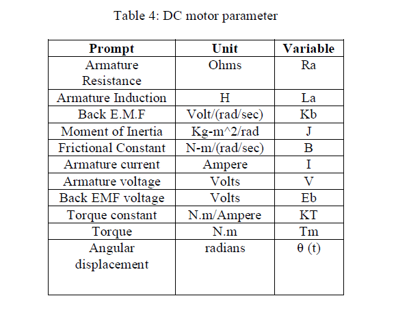
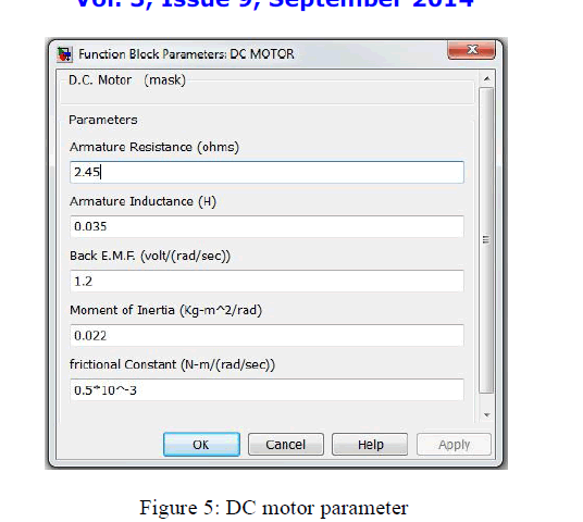
| Last block of simulation model is DC motor, which is in terms of transfer function and to construct it following parameter shown in table 3 are set: |
 |
| Transfer function of DC motor: |
 |
| The values of individual parameter are set by using functional block parameter of DC motor in SIMULINK as shown in figure 5 below: |
 |
RESULT
|
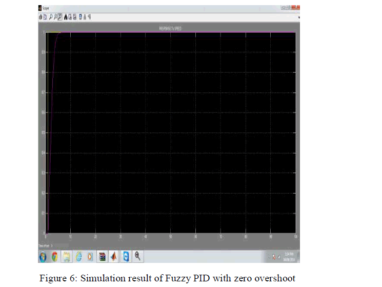
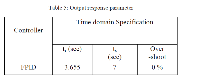
| Figure 6 shows simulation result of Fuzzy PID controller which control DC motor. From figure it is clearly visible that reference or ideal response not exceed by actual output on behalf of which we can say that there is no overshoot or zero overshoot. |
 |
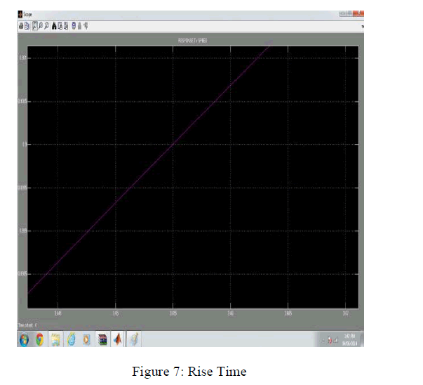
| Figure 7 shows rise time (represented by tr) of the output response is 3.655 this is enlarge view of above result. |
 |
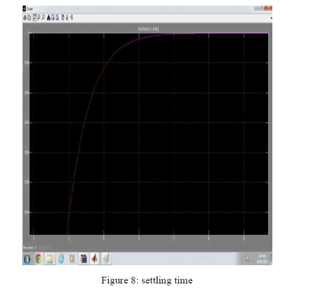
| . Settling time represented by ts. Figure 8 shows settling time of the output response. |
 |
| In following table shows the output response of FPID Controller in term of Rise time, settling time and overshoot. |
 |
FUTURE SCOPE
|
| Illustrated PID controller also has developed with all fuzzy rules for designing the hardware PID chip using VHDL. Then, the synthesize tool has used to get the logic gates of hardware PID modules. Numerous PID controllers be capable of realize on a solo FPGA chip together with coefficient calculation and auto tuning. |
| By reason of the utilization of Arithmetic algorithm, the number of PID controllers on solitary FPGA chip can be increased hugely. The compensation is high processing speed, reduced power consumption and hardware compatibility for implementing on FPGA. The designed FPID chip can be used to the targeted application. There is no doubt in use and application of controller and not only in electronics but also in bio medical equipments for most sensitive disease like insulin pump for diabetic patients, temperature controller etc. |
CONCLUSION
|
| We have developed the Fuzzy PID Controller algorithm using MATLAB/SIMULINK platform. The described PID controller also has developed with all fuzzy rules. Firstly we design the PID controller with transfer function (DC motor) as a plant. But the result of transfer function is poor with only PID. So that fuzzy controller is combined with PID controller. With fuzzy PID controller the performance of transfer function is better than PID controller. Like rise time is increase, settling time is decrease, zero overshoot. |
References
|
- Md. Shabial Islam, Nowshad Amin, Mukter Zaman, M.S. Bhuyan, “Fuzzy based PID Controller using VHDL for transportation application”,n International Journal of mathematical model & method in applied science, volume 2, Issue 2, 2008
- Yu Yongquan, Huang Ying and Zeng Bi, “A PID neural nctwork controller”, Proceedings of IJCNN, Portland, U.S.A, Vol.l-4, pp.1933-1938,2003.
- Amit Kr. Singh, Manjari mehrotra, AK Pandey, “Improvement of the performance of different order system with adaptive fuzzy PIDcontroller”, VJRD-IJEECE, ISSN no. 2231-3346, vol. 2(2), pp27-38, 2012.
- Nasri Sulaiman and Zeyad Assi obaid, “FPGA based fuzzy logic: Design and applications-A review”, IACSIT International Journal ofengineering and technology. ISSN: 1793-8236 Vol.1, No. 5, Dec-2009.
- Yesar Noori Lafta and Aslan Sabah aldeen Abdi, “Snubber Network Design for Triac Driving Single – Phase Industrial Heater by ApplyingFuzzy Logic Method” Eng. & Tech. Journal , Vol.31, 2013.
- Zeyad Assi obaid, Nasri Sulaiman and M.N. Hamidon, “FPGA based Implementation on digital logic design using Altera DE2board”, IJCSNS,vol. 9, no.8, pp 186-19,2009.
- AS El-Wakee, A A Sarhan “Step Response Enhancement of Hybrid Stepper Motors Using Soft Computing Techniques” International Journalof Intelligent Systems and Applications, 2014.
- Lijuan Xing, Shizhong yang & Qianqian Lu, “Self tuning Fuzzy PID controller for temperature control in variable air conditioning system”,International conference on information & automation, pp 2117-2120, IEEE June 2010.
- Sameep singh & Kuldip S. Rattan, “Implementation of a Fuzzy logic Controller on FPGA using VHDL” pp 110-115 IEEE 2003.
- Somsubhra Ghosh, Ranjit Kumar Barai, Samar and Prathana Bhattarcharya, Shubhobrata Rudra, Arka Dutta, Rownick Pyne, “ An FPGA based
- Implementation of a flexible Digital PID controller for a motor control system”, 2013 International conference on computer communicationand informatics(ICCCI-2013), 04-06,IEEE 2013.
- Hassan Talebi Abatari and Abdolreza Dehghani Tafti, “Using a Fuzzy PID controller for path following of a car like Mobile Robot”,International conference on Robotics & Mechatronics, pp 189-193, IEEE Feb 2013.
- K. Ghousiya Begum, D. mercy, H. Kiren Vedi, “An expert system based PIDC for Higher order process”, International journal of computer technology and electronics engineering (IJCTEE) vol.2, issue 5, pp 46-50, oct-2012.
|