Keywords
|
| Series-Compensation, Power Swing, Fault Impedances Calculation and Distance Relay. |
INTRODUCTION
|
| As modern transmission systems become heavily loaded the benefits of series compensation for many of the grid’s transmission lines become more obvious. Clearly, adding fixed series compensationhas long been the preferred solution for optimizing performance in very large bulk transmission corridors. Installing a capacitive reactance in series in a long (typically more than 200 km) transmission line reduces both the angular deviation and the voltage drop, which loweringlosses, increases the loadability and stability of the line. Series compensation provides increased transient (angular) stability of a power corridor and increased voltage stability of the grid. It also improves the voltage profile along the power corridor and optimizes power sharing between parallel circuits.Unfortunately, the series capacitor can undermine the effectiveness of many of the protection schemes used for long distance transmission lines. The introduction of the capacitance in series with the line reactance adds certain complexities to the effective application of impedance based distance relays. However, series compensation increases the fault current level and may also cause generator sub-synchronous resonance. |
| Power system at steady operation maintains a balance between the generation and load. System disturbances, such as line switching due to the fault, generator disconnection, and switching ON/OFF large loads cause oscillations in rotor angles among generators and can result in severe power-flow swings. As a consequence, the apparent impedance seen by a distance relay may fall within its operating zone. This may be misinterpreted as a fault and the relay would trip the line unnecessarily. |
RELAYING PROBLEMS ASSOCIATEDWITH SERIES COMPENSATION
|
| The introduction of the capacitance in series with the line reactance adds certain complexities to the effective application of impedance based distance relays. The relay will attempt to look at the ratio of voltage to current to determine the distance to the fault in order to decide if the fault is in or out of its zone of protection. It is of course possible to correct the settings of the relay when it is known that the capacitor is always going to be part of the fault circuit. However, that is not always known. By canceling some of the line’s series inductance, the series capacitor can make remote forward faults look as if they are in zone one of the relay when the capacitor is switched into the transmission line circuit and the relay setting rules are based on no capacitor in the fault loop (i.e. they can cause the relay to “overreach”). Under these conditions, close-in faults can appear to be reverse faults due to voltage reversal (voltage inversion) [2]. Clearly, some scheme must be used to protect these lines. One approach is to slow down the operation of the relay so that the capacitor protection system in use (MOV and/or spark gap and/or circuit breaker) will have time to operate and remove the capacitor (or short circuit its terminals) from service. Then the traditional impedance relay will function properly. |
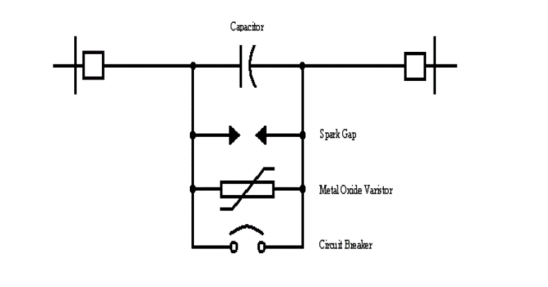
Figure 1.MOV protection |
| As shown in Fig, an MOV protection, a triggered air gap protection and a bypass circuit breaker are across the capacitor. A damping circuit between the capacitor and the triggered air gap limits the current through the air gap when it fires. The MOV, the air gap and the circuit breaker make up the total capacitor overvoltage protection. With short circuits on the line, the voltage across the capacitor could build up to extremely high values, especially under resonant system conditions [1]. The MOV in this case will limit the voltage to some predetermined safe level, typically 2 pu where 1 pu is the voltage across the capacitor with rated current flowing through it. In the case of the MOV, when the external fault is cleared and the overvoltage across the capacitor disappears, the MOV stops conducting and the capacitor is back in service. Both the MOV and the air gap, when conducting, change the impedance as 'seen' by distance measuring relays. With the proposed application in the Ontario Hydro system of a relatively large amount of compensation of 65 % at one terminal in each circuit of a double circuit line, a study of the effect of the compensation, the MOV memory polarization and the location of the potential source on the performance of distance relay elements was considered desirable. Performance aspects related to direct underreach/ permissive overreach protection schemes were also of interest. |
CAUSES OF POWER SWINGS
|
| In the normal operation, the electric power system maintains a dynamic and delicate balance between generation and load. A disturbance, such as a sudden change of load, a power system fault, or a trip of a generator, may break the balance and cause oscillations in generator rotor angles. The oscillations are due to the large inertia of the generators and the relatively slow control of input mechanical power.During a power swing, voltages and currents in the power grid will show a certain amount of oscillations in magnitude and phase angle, which can cause unwanted operation of distance protection, relays [9]. Moreover, the operation of protective relays may exacerbate system stability and can lead to cascading power outages such as that which occurred on August 14th 2003. |
IMPEDANCE TRAJECTORIES DURING POWER-SWING
|
| The algorithm is based on the fact that a power swing can be best detected by analyzing its impedance trajectory behavior in a certain time window. As it is power swing impedances generally move in elliptical trajectories, which can be further analyzed to determine if the power swing is stable or unstable (OOS). A power swing can be detected even before the impedance trajectory enters the power swing detection zone. Once the impedance trajectory moves into the power swing detection zone, the distance protection functions can be blocked if the power swing blocking (PSB) element is enabled [9]. |
QUADRILATERAL RELAY ALGORITHM
|
| Before the advancement of comparator andMicroprocessors, most relays were based on a balanced beam structure or induction cup unit, which generate only continuous characteristics such as a circle or a straight line. Since quadrilateral characteristics are discontinuous its characteristics cannot generate by electro mechanical relays devices. With this type of characteristic, the tripping area can be arranged closely to enclose the desired tripping area[6]. The ability to detect significant resistance associated with the restriction is important. With the ability to closely enclose the desired trip area results in a more secure application. Quadrilateral elements with plain reactance reach lines can introduce reach error problems for resistive earth faults where the angle of total fault current differs from the angle of the current measured by the relay. This will be the case where the local and remote source voltage vectors are phase shifted with respect to each other due to pre-fault power flow. This phase difference can be overcome by using a phase current for polarization of the reactance reach line.Polygonal impedance characteristics are highly flexible in terms of fault impedance coverage for both phase and earth faults. |
ZONE PROTECTION
|
| Throughout all transmission lines there will be three protection zones which are used to protect a line section and to provide backup for the remote section. These zones and typical settings are illustrated in Fig. 1 which shows zones at several locations [14].Zone 1 is set for 80 to 90% of the line impedance GH operate instantaneous to ensure that there is no risk in the Zone 1 protection due to errors in the current and voltage transformers, inaccuracies in line impedance data provided for setting purposes and errors of relay setting and measurement. Zone 2 is adjusted for 100% of the line GH, plus approximately 50% of the adjacent line HJ which operates through a timer T2.Zone 3 is Offset zone protection, 100% of transmission line GH as well as 120% of adjacent second line is protects by Zone 3 in forward direction which operates through a timer T3 (T3>T2). Zone3 protection provides reverse reach, typically 20% of the protected line section in addition to its forward reach. This provides time delayed local back up protection for bus bar faults and close up to three phase faults not cleared by other protections [4]. |
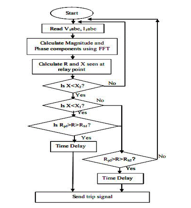
Figure 2.Relay functional algorithm |
FUNCTION AND ALGORITHM
|
| Distance relays generally requires fourteen input signals, namely, harmonic magnitude and phase of three voltages and currents signals each, zero sequence magnitude and phase current to obtain phase quantities. In this work all the 14 signals are obtain from simultaneously taken samples of 6 signals namely three phase to ground voltages and three phase currents [10]. Ground impedance seen at relay point is calculated as |
 |
 |
| K=Degree of compensation, being a ratio of zero to positive sequence impedance of the transmission line that remains constant for all fault locations within the protected lineZ0 =Zero-sequence impedance as seen from the location of the relay to the end of the protected zone. Z1 = Positive-sequence impedance as seen from the location of the relay to the end of the protected zone. The phase impedance at the relay point are calculated as |
 |
| Where Va1, Va2, Ia1, Ia2 are positive, and negative sequence voltages and currents,Va, Vb, Ia, Ib are phase voltages and currentsZPG and ZPPseen at relay point for each phase. Quadrilateral relay classified as an 'Impedance Zone Element', which checks a point described by R and X setting values, whether lies inside a specified region on the impedance plane. If a point defined by ZPG and ZPP is inside the specified region, The Quadrilateral relay produces an output ‘1’ otherwise the output will be ‘0’. Implementation of Quadrilateral relay function in PSCAD/EMTDC is shown in algorithm Figure 2. |
SIMULATION RESULT
|
| Using PSCAD software, the simulation model of a typical 400kV transmission system is set up. Three buses are considered to make better power swing result. When power swing occurs, the voltage and current in the system will fluctuate periodically in wide range, so the impedance seen by the distance relays will also change periodically. |
SIMULATION MODEL
|
| To demonstrate an application of the distance relay in a series compensated transmission line, and the system shown in figure 3 is considered. The system containing three buses, four transmission lines. The transmission line1&2 are compensated by MOV protected series capacitor.Theprotection scheme of each series capacitor including an MOV as shown in figure 3.The distance relay (Quadrilateral relay) R for breaker B1 is considered for the study. The load is added at bus2; this causes a power swing condition in line1 and is observed by the relay R. During this condition, line1 current waveform is shown in Figure 4 respectively. |
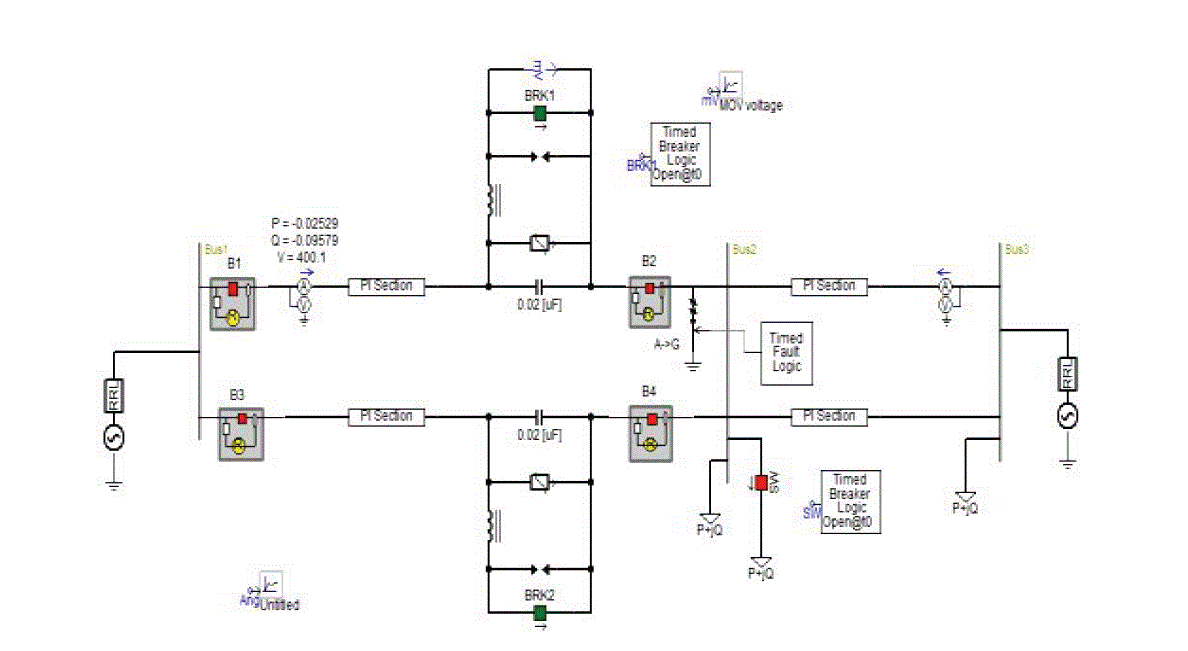 Figure 3.Simulation diagram Figure 3.Simulation diagram |

Figure4.Line1 current during power swing |
| Figure 4 shows the current waveform during the power swing. The current waveform seems to be constant before the additional load. When the load is added power swing occurs and the magnitude of current gets increased. |

Figure 5.Line1 current during fault |
| Figure 5 shows the normal current waveform and when additional load gets added the power swing occurs at some point. The current magnitude gets increased after the power swing. When the fault occurs in the line, the current waveform gets distorted for certain period and then the current magnitude seems to be constant. |

Figure 6.Line1 real power flow during swing |
| The figure 6 shows the real power flow in line 1. When the load gets added in bus 2, oscillation occurs at the real power flow during the power swing. After a certain period the oscillation damps and gets a new steady state. |
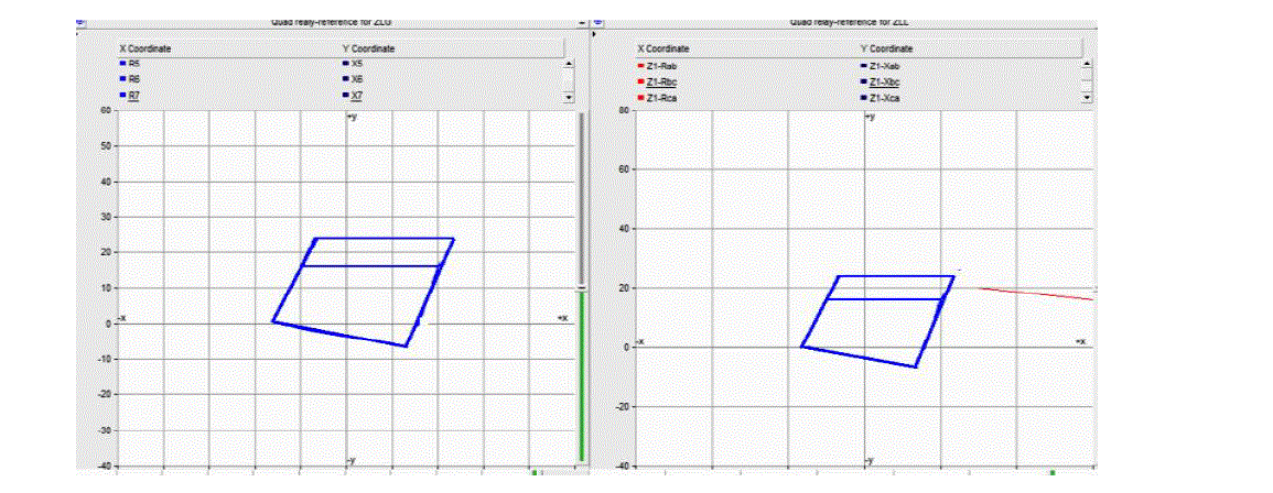
Figure 7.Quadrilateral relay characteristics during power swing |
| Figure 7 shows the quadrilateral relay characteristics. During the power swing period the apparent impedance doesn’t enter into the tripping region. |
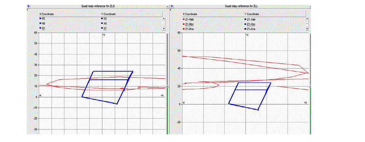
Figure 8.Quadrilateral relay characteristics during fault |
| Figure 8 shows the quadrilateral relay characteristics during fault period. From this characteristics during the fault period the apparent impedance enter into the tripping region. So during power swing condition the quadrilateral relay is doesn’t generate any tripping command, but during the fault period the relay generate tripping command. |
| Figure 9 & 10 shows the voltage drop across the MOV during power swing and fault. |

Figure 9.MOV voltage drop during power swing |

Figure 10.MOV voltage drop during fault |
| From the above waveforms seems to be little modification during power swing condition, but during fault period the modification get high peak magnitude. This will cause the protection problem in fixed capacitor. |
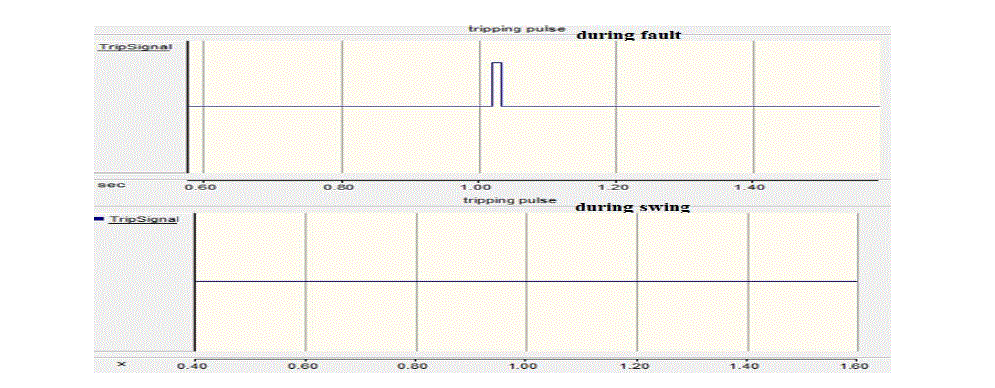
Figure 11.Trip signal |
| Figure 11 shows the tripping commands. From this seems to be no tripping pulse is generated during power swing, but during fault the tripping pulse is generated |
CONCLUSION
|
| This paper represents the performance of QUADRILATERAL relay in various conditions such as power swing and fault condition which occurs inthe series-compensated line.The double-line circuit is considered for test case and analyzed in PSCAD. From the result quadrilateral relay is not tripped when the power swing occurs in the seriescompensated line and it has been worked properly in fault condition. |
References
|
- Esmaeilian, A. Ghaderi, M. Tasdighi, and A. Rouhani, “Evaluation and performance comparison of power swing detection algorithms inpresence of series compensation on transmission lines,” in Proc. 10th Int. Conf. Environment Elect. Eng.,
- Newbould and I. A. Taylor, “Series compensated line protection: System modeling and relay testing,” in Proc. 4th Int. Conf. Develop.Power Protect., 1989, pp. 182–186. May 8–11, 2011, pp. 1842–1848.
- Y. Abdelaziz, A. M. Ibrahim, M. M. Mansour, and H. E. Talaat, “Modern approaches for protection of series compensated transmissionlines,” Elect. Power Syst. Res., vol. 75, pp. 85–98, 2005.
- Craig Muller, P. Eng. “Power system computer aideddesign user’s guide”, Manitoba HVDC Research Centre,September 2005
- D.L. Goldsworthy, "A Linearized Model for MOV-Protected Series Capacitors," IEEE Transactions on Power Systems, Vol PWRS-2, No 4,NOV 1987, pp 953-958
- HarikrishnaM“Performance of quadrilateral relay on EHVtransmission line protection during various faults “.2010 ACEEE
- H. J. Alture, J. B. Mooney, and G. E. Alexander, “Advances in series compensated line protection,” 2008. Online]. Available: www.selinc.com/20081022, TP6340-01
- J. Berdy, "Protection of Circuits with Series Capacitors, " AIEE Transactions on Power Apparatus and Systems, Vol 81, Pt 111, Feb 1963, pp929-935.”
- Paresh Kumar Nayak, Ashok Kumar Pradhan, Senior Member, IEEE, and PrabodhBajpai, Member, IEEE “A Fault Detection Technique forthe Series-Compensated Line During Power Swing” IEEE Trans. Power Del., vol. 28, no. 2, April 2013.
- Y.G. Paithankar , S.R. Bhide, “Fundamental Of PowerSystem Protection”.
|