Keywords
|
| Regulated power supply, Buck, Boost,̉̉ uk&Buck-boost converters, PWM controller, ripple |
I.INTRODUCTION
|
| A DC power supply which maintains the output voltage constant irrespective of AC main fluctuations or load variations is known as regulated DC power supply |
 |
| A regulated power supply consists of an ordinary power supply and voltage regulating device. Fig. 1 shows the block diagram of a regulated power supply. The output of ordinary power supply is fed to the voltage regulator which produces the final output. The output voltage remains constant whether the load current changes or there are fluctuations in the input ACvoltage. |
| A regulated power supply can be built using a simple zener diode as a voltage regulator. Reverse breakdown voltage of the zener diode is used to hold the output voltage constant at a certain load condition. To improve voltage regulation, a negative feedback configuration is used in the regulator. Higher efficiency power supplies use switching regulators which employ fast switching devices. The quality of a power supply depends on its load regulation, line regulation, and output resistance. |
| The DC-DC converters including the buck, boost, buck-boost, and the non invertingbuck boost, produce a unipolar dc output voltage. With these converters, it is possible to increase, decrease, and/or invert a DC voltage. |
| 1. Load regulation |
| The load regulation indicates how much the load voltage changes when the load current changes. The load regulation is defined as: |
 |
| where VFL=voltage at no load current (IL=0) ; VNL=voltage at full load current (Il=IFL) |
| The smaller the load regulation, the better the power supply. A well-regulated power supply can have a load regulation of less than 1%. |
| 2. Line regulation |
| Any change in the line voltage out of the nominal value (i.e., 120V AC) will affect the performance of the power supply. The line regulation is defined as: |
 |
| where VHL=load voltage with high line; VLL=load voltage with low line |
| The smaller the line regulation, better the power supply. A well-regulated power supply can have a line regulation of less than 0.1%. |
| 3. Output resistance |
| The output resistance of a power supply determines the load regulation. If a power supply has a low output resistance, its load regulation will also be low by the relationship: |
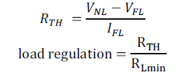 |
| RTH=Output resistance of power supply; IL=full load current (occurs when resistance is minimum) |
| RLmin=minimum load resistance |
II.BACKGROUND
|
| DCconverters are widely used for traction motor control in electric automobiles, trolley cars, marine hoists, forklift trucks,and mine haulers. They provide smooth acceleration control, high efficiency, and fast dynamic response.DCconverter can be used in regenerative braking of DC motors to return energy back into the supply,and this feature results in energy saving for transportation system for frequent stops. DCconverters are used asDC voltage regulators .The power levels encountered in high-efficiency switching converters range from (1) less than one watt, inDC–DC converters within battery-operated portable equipment, to (2) tens, hundreds, or thousands of watts in power supplies for computers and office equipment, to (3) KW to MW, in variable speed motor drives, to (4) roughly 1000 MW in the rectifiers and inverters that interface DC transmissionlines to the AC utility power system. |
III.SCOPE OF THE PAPER
|
| This paper presents a complete scheme containing converters and performance of various regulated power supplies.The exchange of energy between an inductor and a capacitor is used for designing DC-DC converters. Their waveforms are studied and ripple is discussed. |
IV.MODELS OF THE DC-DC CONVERTERS
|
| The field of power electronics is concerned with the processing of electrical power using electronic devices. The components of DC-DC converters are an inductor L,a capacitor C,a controllable semiconductor switch S,a diode D,and load Resistance R.Power electronic switches contain power input and control input ports, and a power output port. The raw input power is processed as specified by the control input, yielding the conditioned output power. In a DC-DC converterthe DC input voltage is converted to a DC outputvoltage having a larger or smaller magnitude, possibly with opposite polarity or with isolation of theinput and output ground reference. |
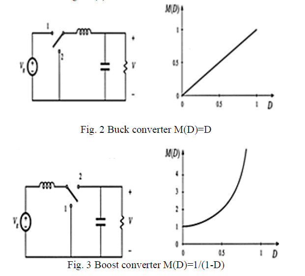
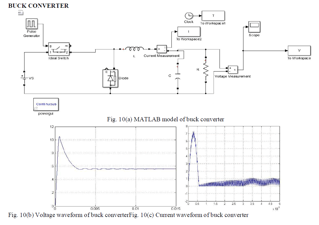
| Buck converter, the most basic topology for switching regulator, model shown in Fig. 10(a). This regulator always stepsdown the voltage as obtained later in Fig. 10(b). |
 |
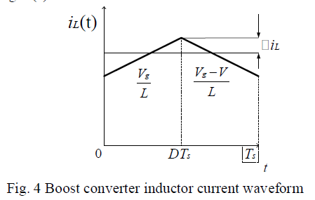
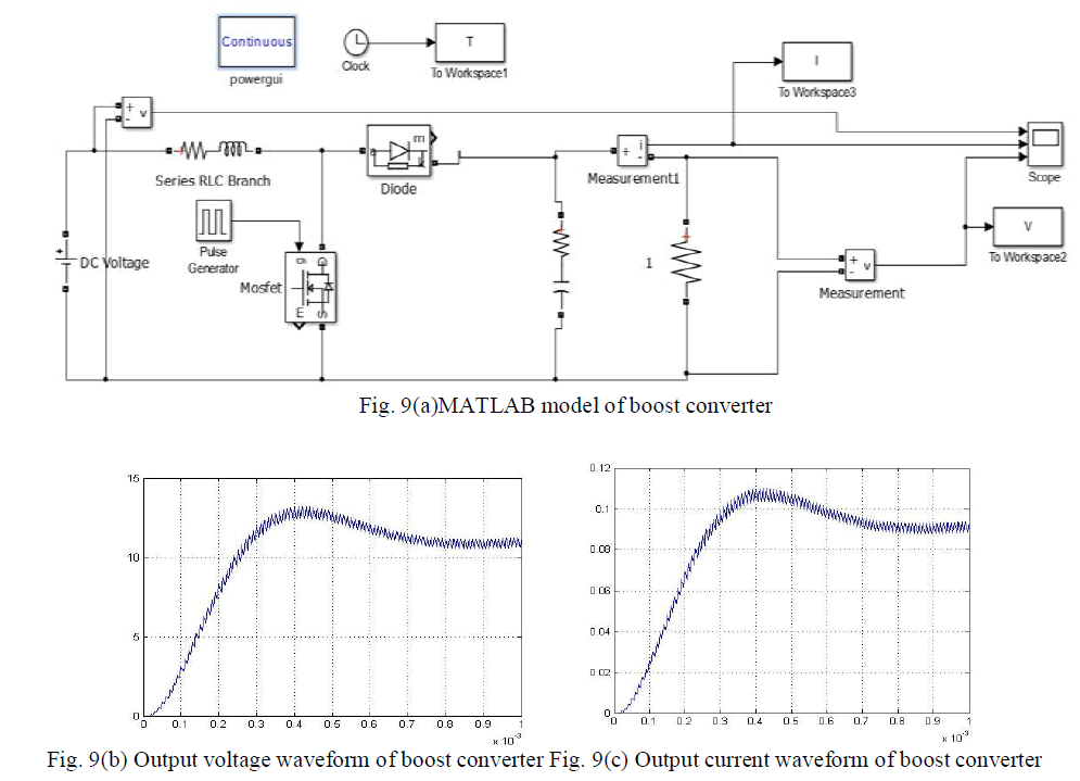
| Boost converter is another well-known switched-mode converter that is capable of producing a DC output voltage greater in magnitude than the DC input voltage as obtained later in Fig 9(b). A practical realization of the switch, using a MOSFET and diode is shown in the model in Fig. 9(a). |
 |
 |
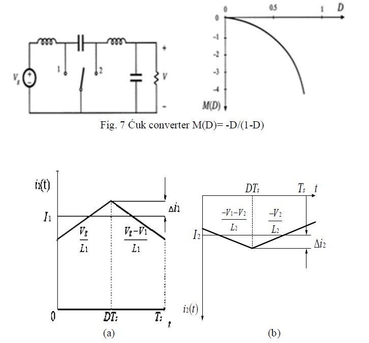
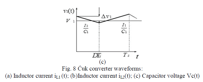
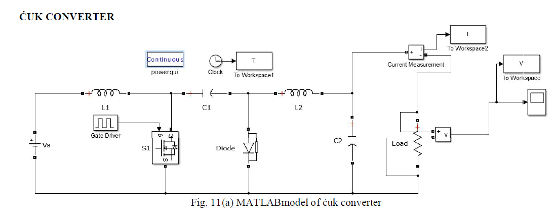
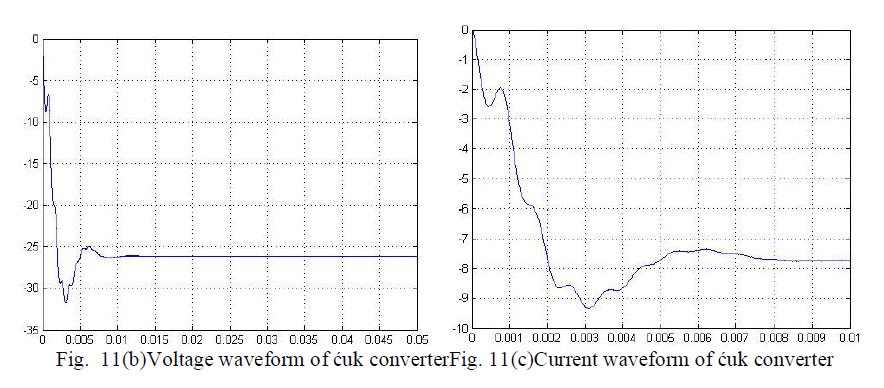
| ̉̉ uk converter performs a DC conversion function similar to the buck-boost converter: it can either increase or decrease the magnitude of the DC voltage, and it inverts the polarity. A practical realization using a transistor and diode is shown in Fig. 11(a). This converter operates via capacitive energy transfer. Capacitor is connected to the input source while the switch is in position 2, and source energy is stored in when the switch is in position 1. This energy is released to the load. The inductor currents and capacitor voltages are defined, with polarities assigned somewhat arbitrarily. The voltage and current ripple magnitudes can also be found. |
 |
 |
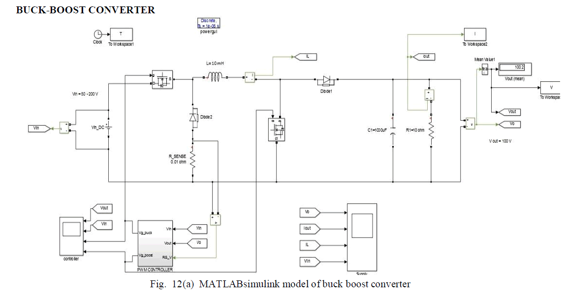
| BUCK-BOOST CONVERTER |
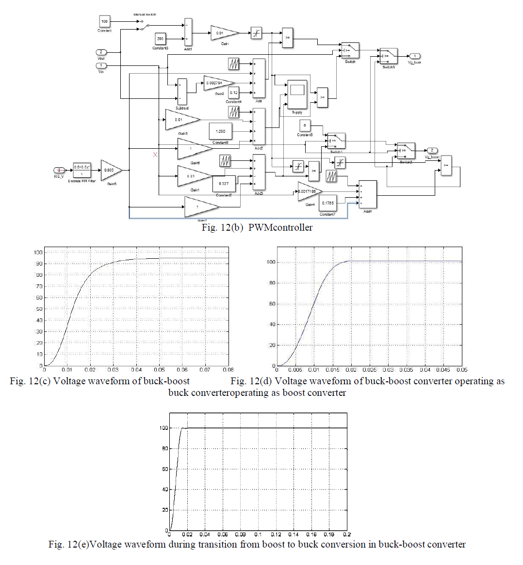
| Buck boost converter acts as a buck converter when applied input voltage is between 110-200Vas obtained later in Fig. 12(c)and as a boost converter when applied input voltage is 50-100V as obtained later in Fig. 12(d) |
V.EXPERIMENTAL RESULTS
|
| BOOST CONVERTER |
 |
 |
 |
 |
 |
 |
V. CONCLUSION
|
| For all four converters,we have assumed that the output voltage is constant and stiff.However,in practice,the capacitor voltage has a small ripple on top of the average value.The smaller the ripples the better the quality of the output voltage is.The ripples in the output voltage can be reduced by increasing the capacitance C or by increasing the switching frequency f.But increasing the capacitance increases the size of the capacitor,which increases the cost and size of the converter.Again,by increasing the switching frequency,the switching losses would increase,decreasing the efficiency of the converter.Hence,a tradeoff is reached between the quality of output voltage and the size of capacitor and switching frequency. The inductor current should be maintained at a positive value. A minimum value of inductance is needed for this purpose. Moreover, if the ripple in inductor current is high,the maximum current in the switches will increase, increasing their rating and cost.However,to limit the ripple in the inductor current, the inductance should be as high as possible; however the size of the converter increases with higher size inductor. So a tradeoff must be reached between the size of inductor, capacitor, switching frequency, and the cost and size of the converter and its efficiency. By knowledge of the slopes of the inductor current and capacitor voltage waveforms, the switching ripple magnitudes may be computed. Inductance and capacitance values can then be chosen to obtain desiredripple magnitudes. |
References
|
- Robert W.Erickson, DraganMaksimovic, “Fundamentals of power electronics” ,Springer Publications;2nd ed.2001 edition
- Michael Tumabcao, “Positive buck boost converter”, IEEE Commune. Mag., vol. 32, pp. 6–13, Oct. 2012.
- L.Zhu, “A Novel Soft-Commutating Isolated Boost Full-Bridge ZVS-PWM DC-DC Converter for Bidirectional High Power Applications,” IEEETrans. Power Electron.,vol 21, pp 422-429, Mar. 2006.
- P.F. Ribeiro, B.K. Johnson, M.L. Crow, and A.Arsoy, and Y.Liu, “Energy storage systems for advanced power applications,” Proceedings of theIEEE, vol.89, issue12, pp. 1744-1756, 2001
- Steigerwald,R.L., “Industrial Electronics, IEEE transactions, vol. IE-31, issue:2
- Seguier,G., Power Electronic Converters-AC/DC Conversion, McGraw-Hill
- Sen,P.C.(Paresh Chandra), Principles of Electric Machines and Power Electronics
|