Keywords
|
| Fuzzy Control, Magnetic Levitation system, MATLAB Simulink, PID controller. |
I.INTRODUCTION
|
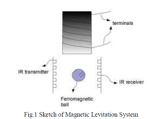
| A Magnetic Levitation System is considered as a good test-bed for the design and analysis of control systems since it is a nonlinear unstable plant with practical uses in high-speed transportation and magnetic bearings. It is a method by which an object is suspended with no support other than magnetic fields. The electromagnetic force is used to counteract the effects of the gravitational force. The maglev system has a bright prospect because it will offer the advantages of lower noise and emissions and better ride quality, as well as potential energy savings compared to conventional guide way systems. The electromagnet along with the suspended metallic ball may be collectively termed as the „plantâÃâ¬ÃŸ. Input to the „plantâÃâ¬ÃŸ is the current flowing in the electromagnetâÃâ¬ÃŸs coil. The plantâÃâ¬ÃŸs output is the vertical displacement of the suspended ball, which is sensed by an optical sensor. Current produced by the sensor is converted to a proportional voltage by means of a „current to voltageâÃâ¬ÃŸ converter. The sensor used in this project is a photovoltaic cell whose current (I) varies linearly with light intensity. As the metallic ball is attracted upwards by the electromagnet it partially covers the sensor, bringing about a change in its surface area exposed to the light source. Also, measurement sensors suffer from noise and track irregularity, which make it hard to control the levitation system. Based on the model of magnetic levitation state feedback system, the paper analyzes the system stability, and finds out the condition and frequency of vibration . In sequence the nonlinear system is simulated to validate the analytical results . A vibrating environment can cause malfunction or failure of mechanical systems and may cause injury to human beings. Therefore, it is envisaged that a form of vibration control or suppressor is needed to compensate the undesirable vibration effect so that it will not damage the systems or cause injury/discomfort to human beings. The performances of the passive systems are highly system dependent as they are unable to adapt or re-tune to changing structural characteristics over time. The idea of active control is that desirable performance characteristics can be achieved through cooperating sensors, actuators and control techniques within mechanical structures. Recently active vibration isolation with various control methods and actuators technology has become a popular topic in vibration control and applied on many systems such as suspension system, precision machine platform, building structures, etc. Here we have used different controller schemes like PID, tuned Fuzzy control in the active control mode to suppress vibration. A Real-Time System responds in a (timely) predictable way when an unpredictable external stimuli arrives. In short, a Real-Time System has to fulfill under extreme load conditions |
| Timeliness: meet deadlines, it is required that the application has to finish certain tasks within the time boundaries it has to respect. |
| Simultaneity or simultaneous processing: more than one event may happen simultaneously, all deadlines should be met. |
| Predictability: the real-time system has to react to all possible events in a predictable way. |
| Dependability or trustworthiness: it is necessary that the real-time system environment can rely on it. |
 |
| (A) MAGNETIC LEVITATION SYSTEM |
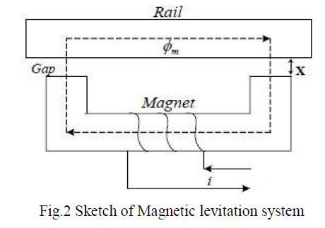
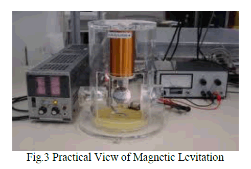
| In this paper we have assumed the Magnetic Levitation System (Fig.2) consists of two subsystems: a) a mechanical subsystem and b) an electrical subsystem. In addition to this we have also taken into account the velocity attained by the object. |
 |
 |
| Transfer Function The transfer function of the system shows the relationship between the input and output to the system. Here current |
| “ i ” is the input and the position of the object |
| “ x ” is the output. Let us consider the following equation |
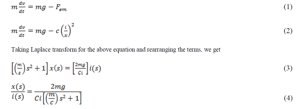 |
| The transfer function of magnetic levitation system (i.e. equation 4) is modified to vibrational controller, thus parameters are taken into this form to obtain the transfer function |
III.PID CONTROL
|
| A proportional-Integral-Derivative controller (PID controller) is a generic control loop feedback mechanism that is widely used in industrial control systems. It attempts to correct the error between a measured process variable and a desired set point by calculating and then implementing a corrective action. The PID controller involves three separate parameters; the Proportional, the Integral and Derivative values, and is accordingly sometimes called threeterm control. P depends on the present errors, I on the accumulation of past errors, and D is a prediction of future errors, based on current rate of change. |
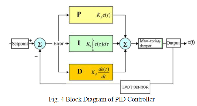 |
Where, |
| Gc - control signal |
| Kp - proportional gain |
| Ki - integral gain |
| Kd - derivative Gain |
| e - Error ; de/dt - derivative error |
| The sum of these three actions is collectively termed as PID control. By "tuning" the „proportionalâÃâ¬ÃŸ, „IntegralâÃâ¬ÃŸ and derivativeâÃâ¬ÃŸ gains, the PID controller can be made to provide control action in accordance with specific process requirements. The proportional gain is precisely adjusted to achieve minimum rise time. However, increasing Kp makes the transient response worse by introducing large overshoots. Ki is varied to reduce the steady-state errors and finally Kd is adjusted to improve unwanted overshoots and to decrease the systemâÃâ¬ÃŸs settling time. |
| A) PID TUNING |
| PID tuning is required and used to tune the parameters of the controller which is said to be Kp Ki Kd values ie., tuning parameters. Zeigler Nichols method is used to tune a parameter value which is a closed loop method. |
| ZEIGLER NICHOLS METHOD |
| This method targets plants that can be rendered unstable under proportional control. The steps for tuning a PID controller are as follows: Using only proportional feedback control: |
| 1. Reducing the integrator and derivative gains to 0. |
| 2. Increasing Kp from 0 to some critical value Kp = Kcr at which sustained oscillations occur. |
| 3. Note the value Kcr and the corresponding period of sustained oscillation, Pcr The controller gains are now specified as in Table |
 |
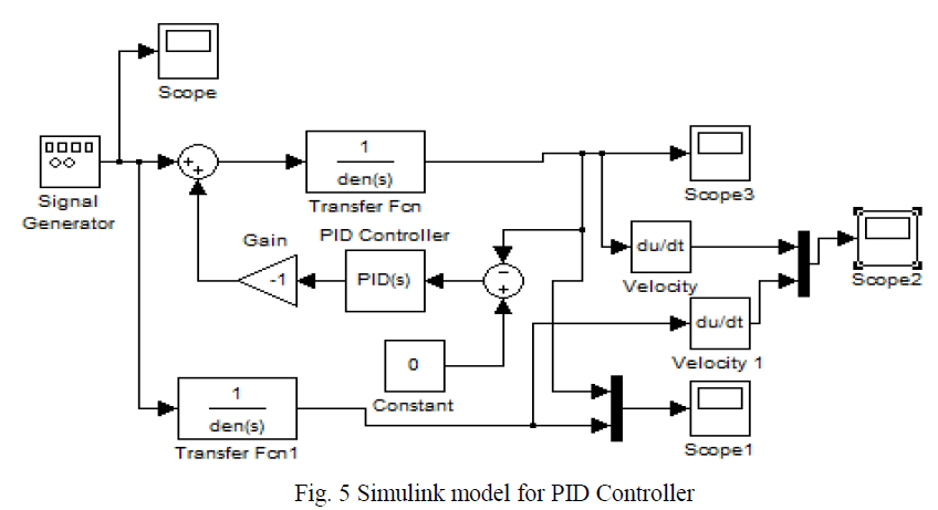
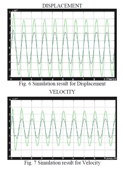
| B) SIMULATION OF PID CONTROLLER |
 |
 |
IV.FUZZY CONTROLLER
|
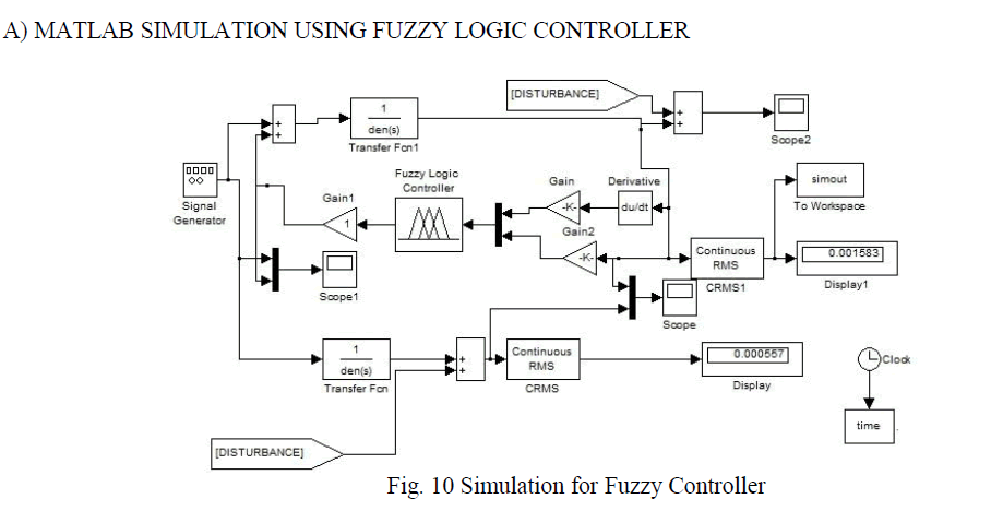
| A fuzzy control system can be considered as a real time expert system, which performs the control tasks in a human-like way and also can technically deal with the approximated information to control systems that have uncertain characteristics. Due to the effect of electromagnet, levitation system is unstable. So, it is difficult to control the levitation using simple PID controller. Because the parameters of the conventional PID controller are fixed during control, it cannot respond in various situations. For this reason, the PID turning method is not suitable with the levitation system. Specially, fuzzy logic is useful to find optimum adjustments of the controller. Moreover, the fuzzy controller can improve the stability of the levitation system. To apply the fuzzy logic controller to the magnetic levitation, certain properties of the system are exploited so that the design of the controller can be made easier. The system under control is described in terms of some linguistic variables. |
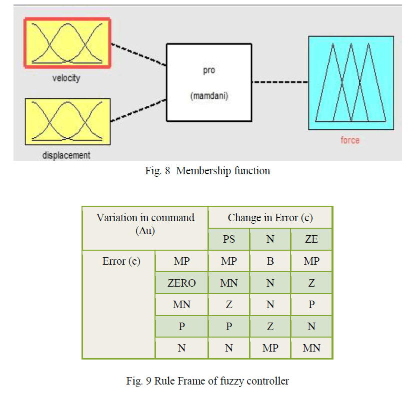 |
| The FLC has two inputs which are error and change of error with output being the change of voltage. The control tasks are performed by using some rules set forth in a rule base. The inference rule used is fuzzy inference scheme. It takes three steps to design a fuzzy controller: fuzzification, inference rules and defuzzification. In the first step, the values obtained from a sensor are transformed into values of the corresponding linguistic variable. The second step performs the fuzzy inference, giving the linguistic values of the control variables. In the third step, these linguistic |
| values are transformed to the numerical value of the control variable in order to perform the required task. After executing the three steps, the controller is fine tuned in an iterative way. The air gap deviation fuzzy set has five membership functions and the air gap deviation velocity has five. |
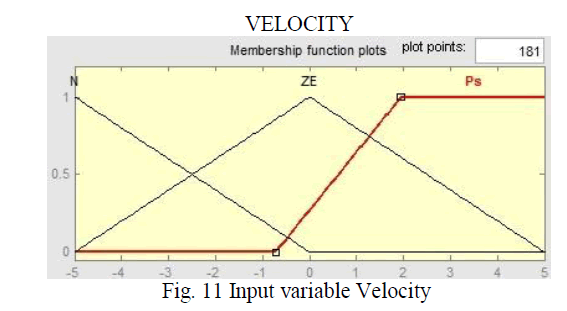
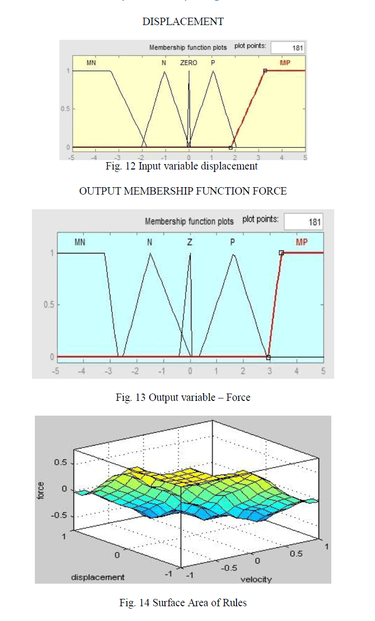
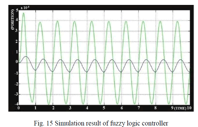
| Fuzzy Toolbox has Matlab software. The ranges of the inputs and output is [-1 1]. All have 7 membership functions. Increasing the number of membership functions, the rule base becomes bigger with increased calculation time. The use of triangular membership functions which become narrow around zero, results in an accurate control. The linguistic “output” variable is the voltage applied to the magnet related to the dc link voltage. Its fuzzy set has seven membership functions. Memberships of Inputs and Output Fuzzy Controller. The next step after designing the membership functions is to write the rules of the fuzzy controller. These rules are chosen based on knowledge base . Table 1 shows the rules base as a matrix |
 |
| B) MEMBERSHIP FUNCTIONS OF FUZZY INPUT MEMBERSHIP FUNCTIONS |
 |
 |
 |
V.CONCLUSION
|
| Conventional PID controllers have poor performance when dealing with nonlinear plants outside the domain for which they have been designed. However, they can help solve some of the problems that designers of fuzzy system are faced with, like: setting the controller gains or choosing other fuzzy parameters. The experimental rig in the form of an active vibration system was successfully developed and experimented. From the results obtained, it is clear that the Fuzzy Logic Controller gives a much better performance than the PID. A fuzzy control strategy that evolved from heuristic knowledge and classical control methods was presented in this paper. Fuzzy controllers make the tracking error sufficiently small enough to achieve lesser vibration and significantly improves the levitation performance without changing the controller algorithm or increasing the cost or complexity of the system enabling the set-up , a potential tool for micromanipulation and micro positioning purposes. |
References
|
- D. Brakensiek, G. Henneberger “Design of a Linear Homopolar Motor for a Magnetic Levitating Transportation Vehicle”, Proc. of the 3rdInternational Symposium on Linear Drives for Industry Applications(LDIA 2001), Nagano, Japan, pp. 352-355.
- Stegemann H., Worlitz F., Hampel R. “Fuzzy logic application for magnetic bearings”, Proceedings of the East West Fuzzy Colloquim 2000,Zittau, 2000.
- Driankov D., Hellendoorn H., Reinfrank M., “An introduction to fuzzy control”, Springer Verlag, p. 2, 1993.
- Lo Verso G., Trapanese M., “A Fuzzy Control Technique for a Magnetically Levitated System”, Proc. Maglev`95, Bremen, November 1995.
- Santisteban J.A., Mendes S., “Fuzzy Control of an Axial Magnetic Bearing”, Proc. Maglev`2000, Rio de Janeiro, June 2000.
- Karl Johan Astrom., “PID Control”, Control system design Lecture notes for ME 155A, chap2, 2002.
|