Keywords
|
| serrated structures, WLAN, Bluetooth, and GSM. |
INTRODUCTION
|
| Microwaves are used in various fields in our daily life. At micro wave frequencies the physical size of the antenna is very small, enough to produce desired directivity. Various applications like Bluetooth, Wifi, Wlan, etc requires an antenna which consumes very less space and which can be easily mounted in communication system. One such design is micro strip patch antenna. |
| Recently, the demand for the design of amicro strip patch antenna with triple- or multiband operation has increased since such an antenna is vital for integrating more than one communication system in a single compact system to effectively promote the portability of a modern personal communication system. For this demand, the developed antenna must not only be with a triple/multiband operation but also have a simple structure, compact size, and easy integration with the circuit. Among the known triple/multiband antenna prototypes, serrated structured patch antenna is widely used because of its ease of integration, low cost, and versatile structure for exciting wide impedance bandwidth, dual- or multi resonance mode, and desirable radiation characteristics. |
| In this paper a design of micro strip patch antenna which works at multiple frequencies is proposed. Micro strip patch antenna uses patches on the top, a di electric substrate at middle and a conductive layer ground as bottom layer. The required design is obtained by using serrated structure, which means the patch is reformed in to different shapes. The dimensions of the patch, length and breadth and height of substrate are key requirements for a design of micro strip patch antenna. |
DESIGN CONSIDERATIONS
|
| A micro strip antenna consists of a two parallel conducting layers separated by a single thin di electric substrate. The lower conducting substance acts as ground plane and the upper conductor acts as radiator. Larger ground plane gives better performance but off course makes antenna big size. Micro strip antenna has different shapes like rectangle, circular, square, triangle, for better performance we use rectangle micro strip patch antenna. The resonant frequency is determined by resonance frequency. The difference between electrical and physical size is mainly depends on PCB thickness and di electric constant. For the performance evaluation different patch that we used here is quartz glass, Taconic, RD 4003, quartz crystal and RT duriod 5880. The size of the substrate determines the performance of the micro strip patch antenna. |
| In this paper the substrate dimensions taken along x- axis and y- axis is 13 cm. the substrate thickness is 0.67 cm. The coaxial inner and outer radius is 0.104 cm and 0.354 cm. For a good performance, a substrate having low di electric constant is preferred because I provides good efficiency, larger band width and good radiation. |
SUBSTRATES
|
| Different substances are used in this present simulation work and their properties are mentioned as follows. RT/duroid 5880LZ filled PTFE composites are designed for exacting strip line and micro strip circuit applications. The RT-duroid is a low density, lightweight material for high performance weight sensitive applications. The very low dielectric constant of RT/duroid 5880LZ laminates is uniform from panel to panel and is constant over a wide frequency range. Applications include airborne antenna system, lightweight feed networks, Military radar systems, Missile guidance systems and Point-topoint digital radio antennas. The RT-duroid substrate of dielectric constant 2.2 and loss tangent of 0.0009 is taken in this present work. |
| Roger RO 4003 series high frequency circuit materials are designed for performance sensitive, high volume application, and ideal for broad band applications. This material is a rigid, thermoset laminate that is capable of being processed by automated handling systems and scrubbing equipment used for copper surface preparation. Quartz glass applications mainly include poly silicon substrates for LCD and fiber optics, substrates for high frequency RF applications, micro fluidic substrates, Nano imprint templates etc. |
SIMULATION RESULTS
|
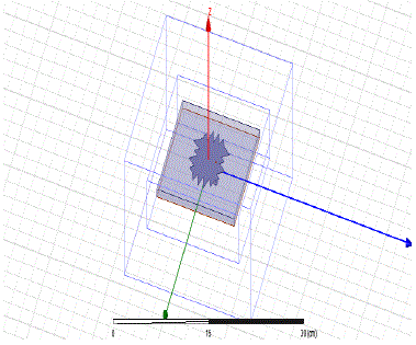 Figure (1) – HFSS simulated design using serrated structures. Figure (1) – HFSS simulated design using serrated structures. |

Table (1) substrate materials with permittivity |
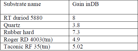
Table (2)- gains when different substrates used |
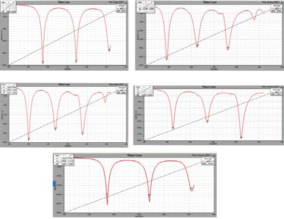
Figure (2) Return loss of different substrates |
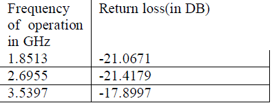
Table (3)-return loss of RT duriod 5880 |

Table (4)-return loss forTable (5) - return loss for quartz taconi RF-35(tm) |
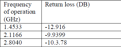
Table (5) - return loss for quartz |

Table (6) – return loss of roger RD4003 (tm) |

Table (7) – return loss for rubber hard |
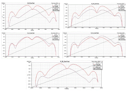
Figure (2) – 2D gains of different substrates. |
| The figure (2) gives the gains of different substrates with different di electric constant values. The gains of different substances are as follows 8 DB, 3.8 DB, 7.3DB, 4.9DB, 3.2 DB, 8DB for different di electric constants as 2.2, 3.78, 3, 3.65, 3.78, and 2.2 respectively |
| Radiation pattern is a mathematical function or graphical representation of the radiation properties of the antenna as a function of space coordinates. Radiation properties include power flux density, radiation intensity, field strength, directivity phase or polarization. In practice, the three dimensional pattern is measured and recorded in a series of two dimensional patterns. For most practical application, a few plots of for some particular values of Phi , plus a few plots as a functions of phi for some particular values of , give most of the useful and needed information |
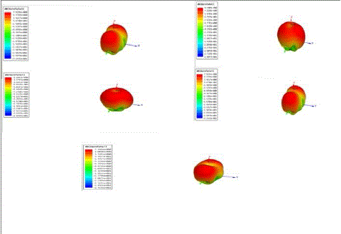
Figure (3) – 3d gain |
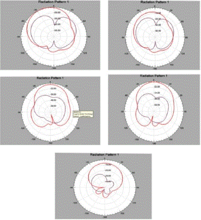
Figure (4)- radiation pattern 1 |
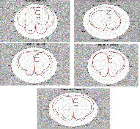
Figure (5) – radiation patter 2 |
CONCLUSIONS
|
| Performance of micro strip serrated patch antenna based on different materials is investigated and their performance characteristics are shown and tabulated in this present work. We observed that by increasing the di electric constant of substrate material the band width is decreasing and the gain values are decreased. |
ACKNOWLEDGEMENTS
|
| Authors like to express their thanks to the management ofLBRCE for their continuous support and encouragement during this work. Especially authors like to express their thanks to Dr.E.V.Prasad Director, LBRC of Engineering for providing Excellent R&D for the completion of this work. |
References
|
- D.M. Pozar and D.H. Schaubert, The Analysis and Design of Micro strip Antennas and Arrays, IEEE Press, pp. 53,april-1995..
- S.Sudhrani, P.RakeshKumar”Microsrtip circular patch array antennaFor electronic toll collection” IJRET, ISSN: 2319-1163, Volume: 2 Issue: 1,pp52-54,jan 2013
- D.Rakesh, P.RakeshKumar,SriKavya, K.Prabhu Kumar, S Bala Durga Prasad, Performance Evaluation Of Microstrip Square Patch Antenna OnDifferent Substrate Materials, Journal of Theoretical and Applied Information Technology, www.jatit.org, Vol 26 No 2, April 2011.
- B.T.P.Madhav, VGKM Pisipati, P.Rakesh Kumar, K.V.L.Bhavani, S.Balaji, V.Shiva Kumar, “Dual Frequency Microstrip Rectangular Patch Antennaon Liquid Crystal Polymer Substrate”, International Journal of Engineering Sciences Research-IJESR http://technicaljournals.org ISSN: 2230-8504; e-ISSN-2230-8512, Vol 01, Issue 02, May, 2011.
- D.Rakesh,P.Rakesh,Kumar,B.T.P.Madhav,Prof.HabibullaKhan,Ch.SriKavya,K.Prabhukumar,S Bala Durga Prasad “Systematic evaluation of squarepatch antenna performance based on permittivity of the material”,International Journal Of engineering Science and Technology (IJEST),ISSN:0975-5462,VOL.3 NUMBER .3 MARCH 2011.
- Md. Maruf Ahamed, Kishore Bhowmik, Md. Shahidulla,Md. Shihabul Islam, Md. AbdurRahman”Rectangular Micro strip Patch Antenna at 2GHZ onDifferent Dielectric Constant for Pervasive Wireless Communication”International Journal of Electrical and Computer Engineering (IJECE)Vol.2, No.3,ISSN: 2088-8708, pp. 417 ~ 424, June 2012
- D.RAKESH, P.RAKESH KUMAR, PROF. HABIBULLA KHAN ,K CH SRI KAVYA,B.T.P.MADHAV, K.PRABHU KUMAR, S BALA DURGAPRASAD “Performance Evaluation of micro strip square patch antenna on different substrate materials”Journal of Theoretical and Applied InformationAnd Technology. Vol 26 no 2,ISSN-1992-8645, www.jatit.com. Pp 97-106, April 2011
|