Keywords
|
| WiMAX, IEEE 802.16, OFDMA, QPSK, Channel coding. |
INTRODUCTION
|
| WiMAX is an IEEE 802.16 standard based technology responsible for bringing the Broadband Wireless Access (BWA) to the world as an alternative to wired broadband. The WiMAX standard 802.1 6e provides fixed, nomadic, portable and mobile wireless broadband connectivity without the need for direct line-of-sight with the base station. The model implemented in this paper is based on the WiMAX which has the following characteristics[3]. |
| Standard: IEEE 802.16e |
| Carrier Frequency: Below I1IGHz |
| Frequency Bands: 2.5GHz, 3.5GHz, 5.7GHz |
| Bandwidth: 1.5MHz to 20MHz |
| Radio Technology: OFDM and OFDMA |
| Data Rate: 70 Mbps |
| Distance: 10km |
| The significance of building a model for this standard can be established by considering the effect that a model can bring on the overall project development lifecycle. Mathworks, the vendors for the Matlab software have put together a White Paper [4] on this topic of creating an executable specification in Simulink for WiMAX and that paper is a useful resource to follow and build a model from scratch. |
THE WIMAX MODEL
|
| The model presented in this paper is built on the following parameters [1,2]. |
| Scenario: 16-Channel Full Bandwidth |
| Modulation: QPSK (QPSK is same as 4-QAM) |
| RS Code Rate: 3/4 |
| CC Code Rate: 5/6 |
| The modelling setup includes Matlab R2010a, Simulink10 and Communications Blockset running on Windows XP SP2 Matlab Simulink includes all the mandatory function blocks as specified by the standard documents. The Model itself consists of three main components namely transmitter, receiver and channel. Transmitter and receiver components consist of channel coding and modulation sub-components whereas channel is modelled as AWGN and Fadding channel. |
A. IEEE Standard 802.16e:
|
| IEEE Standard 802.16e is different from the previous versions of the standard in the sense that 802.16e adds the feature of mobility to the wireless broadband standard. The formation of the IEEE 802.16 Working Group on Broadband Wireless Access Standards was initiated in August of 1998 by the National Wireless Electronics Systems Testbed at the U.S. In April of 2002 the 802.16-2001 standard was officially published. This standard has since been superseded by the 802.16-2004 standard which includes material from the original 802.16-2001 standard as well as the 802.16.2-2001, 802.16c-2002, and 802.16a-2003 standards. The IEEE 802.16 Working Group is a part of the IEEE 802 LAN/MAN Standards Committee and continues to work on a number projects. |
B. Frequency Bands:
|
| The 802.16 standard defines a number of air interfaces that make use of a frequency band that can be divided into one of three categories: 10-66 GHz licensed bands, licensed bands below 11 GHz, and unlicensed bands below 11 GHz. Table 1 summarizes the air interface designations and their applicable category of frequency bands. |
(a) The 10-66 GHz Licensed Bands:
|
| These frequency bands have a short wavelength that requires line-of-sight (LOS); however, the multipath interference is negligible. The bands allow for data rates in excess of 120 Mb/s and coupled with an environment that is well suited to the implementation of point-to-multipoint (PMP) access and the frequency bands are well suited to small office/home office (SOHO) all the way up to large office applications. |
(b) Below 11 GHz Licensed Bands:
|
| The second category of licensed bands below 11 GHz requires special note due to the characteristics of the frequency bands. Due to the longer bandwidth of the frequency range, LOS is not necessary and the multipath interference may be significant. As such, the ability to support near-LOS and non-LOS (NLOS) applications requires additional PHY requirements to be fulfilled such as advanced power management techniques, interference mitigation/coexistence, and multiple antennas. |
(c) Below 11 GHz License-exempt Bands:
|
| The final category below 11 GHz, typically using the 5-6 GHz bands. The operating environment of these bands is similar to those of the 11 GHz licensed bands; however, the license-exempt status of the bands introduces additional interference from the co-existence of other devices within the range, as well as regulatory constraints that limit the radiated power. To overcome these problems mechanisms such as dynamic frequency selection is introduced to the PHY and MAC of the air interface. |
ORTHOGONAL FREQUENCY DIVISION MULTIPLE ACCESS
|
| Data transmission in downlink is depending on OFDMA, which is an assured technique to give an efficient access over high-speed wireless networks. Moreover, it is acceptable for broadcasting even in Multiple-Input Multiple-Output (MIMO) scenarios [5]. OFDMA acquires high spectral efficiency in multiuser ambiance by dividing the total convenient bandwidth into confined sub-bands to be distributed by users in an efficient manner. Different bandwidths are reinforcement (from 1.25 to 20 MHz) holding subcarrier spacing unchanged and, as a result, the number of subcarriers changes accordingly. This technology will afford broad-band wireless access at data rates of multiple Mbit/s to the end-user and within a range of several kilometers. |
| OFDMA at the physical layer, in combination with a Medium Access Control (MAC) layer, supports an optimized artifice allocation and Quality of Service (QoS) support for distinct types of services [6]. |
| The OFDM signal used in LTE consist of a maximum of 2048 different sub-carriers having a spacing of 15 kHz. Al-though it is necessary for the mobiles to have capability to be able to draws all 2048 sub-carriers, not all need to be transmitted by the base station which only needs to be endowing to support the transmission of 72 sub-carriers. In this way all mobiles will be endowing to talk to any base station. |
A. Channel Coding:
|
| Channel coding can be described as the transforming of signals to improve communications performance by increasing the robustness against channel impairments such as noise, interference and fading. Channel Coding can be described as a three phase process including Randomization, Forward Error Correction and Interleaving. |
(a) Randomization:
|
| Randomization is carried out after the data packet is received from the higher layers. Randomizer operates on a bit by bit basis. The main component of the data randomization is a Pseudo Random Binary Sequence generator which is implemented using Linear Feedback Shift Register. |
(b) Forward Error Correction (FEC):
|
| Forward Error Correction consists of concatenation of Reed-Solomon Outer Code and a rate compatible Convolutional Inner Code. |
| The purpose of using Reed-Solomon code to the data is to add redundancy to the data sequence; it helps in correcting block errors that occur during transmission of the signal. |
| RS encoder is based on Galois Field Computations for calculations of the redundant bits. WiMAX uses a fixed RS Encoding technique based on GF(2 ) which is denoted as RS(N = 255, K = 239, T =8) |
| Where: |
| N = Number of Bytes after encoding |
| K = Data Bytes before encoding |
| T - Number of bytes that can be corrected |
(c) Convolutional Encoding:
|
| A convolutional code is a type of FEC code that is specified by CC(m, n, k), in which each in-bit information symbol to be encoded is transformed into an n-bit symbol, where m/n is the code rate (n > m) and the transformation is a function of the last k information symbols, where k is the constraint length of the code [5]. |
| In WiMAX Physical Layer each RS block is encoded by the binary convolutional encoder, which has a code rate of 7/2 and a constraint length equal to 7. This encoder has two binary adders X and Y and uses two generator polynomials, A and B. The output of the convolutional encoder is then punctured to remove the additional bits from the encoded stream. |
(d) Interleaving:
|
| Interleaving is done by spreading the coded symbols in time before transmission. The incoming data into the interleaver is randomized in two permutations. First permutation ensures that adjacent bits are mapped onto non-adjacent subcarriers. The second permutation maps the adjacent coded bits onto less or more significant bits of constellation thus avoiding long runs of less reliable bits. |
B. Modulation
|
| The interleaver records the data and sends the data frame to the IQ mapper. The function of the IQ mapper is to map the incoming bits of data from interleaver onto a constellation. In the modulation phase the coded bits are mapped to the IQ constellation, starting with carrier number -100 on up to carrier number + 100. Guard band, pilot carriers and DC carrier are inserted in the structure before using the IFFT to convert the frequency 119 domain signals into time domain. |
SIMULATION RESULTS
|
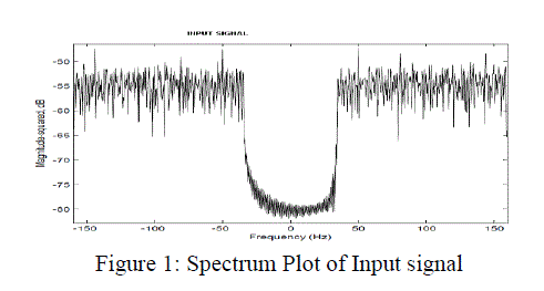
| Simulink model of OFDM and OFDMA are designed to perform bit error rate calculation under fadding hannel. Figure 1 shows spectrum scope of signal ptior to OFDM modulation for an input. |
 |
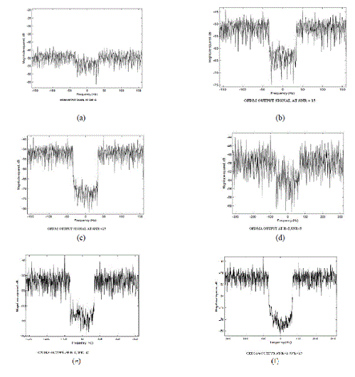
| Figure 2 shows received output after OFDM modulation in presence of Rayliegh fading channel with AWGN noise. 2(a) is response at SNR 5 db. We can compare figure 1 the spectrum of input with figure 2(a) to visualize effect of fading and noise during OFDM transmission in a WiMax model.Similarly we changed SNR to increase signal strength and find the spectrum response at SNR 15dB and 25dB(figure 2(b,c)). |

Figure 2: (a),(b) &(c) Spectrum of receiver output after OFDM modulation in presence of Raliegh fading and AWGN channel at SNR 5,15,25 dB.2(d),(e) & (f) are spectrum for same input but using OFDMA at repetition of R=2. |
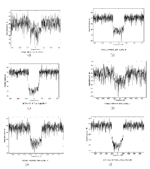
| Similarly we obtained the response using OFDMA technique at different repetition factor R-2,4,6.Figure 3(a,b)&(c) for R=2 and SNR 5,15,25dB.Figure 3(d),(e)&(f) for R=6. |

Figure 3: (a),(b) &(c) Spectrum of receiver output after OFDMA modulation in presence of Raliegh fading and AWGN channel at R=4,SNR 5,15,25 dB.2(d),(e) & (f) are spectrum for same input but using OFDMA at repetition of R=6. |
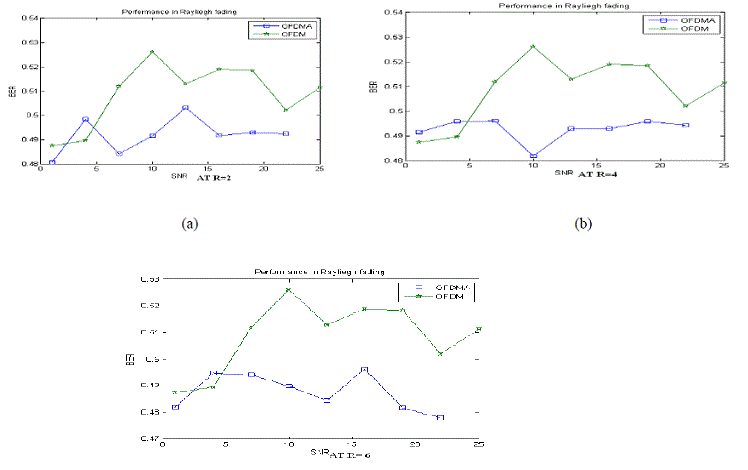
| We can see the performance using BER calculation plot of the OFDM and OFDMA model in figure 4(a),(b) and (c) to compare their performance. |
 |
| TABLE I BER CALCULATION OF OFM/OFDMA MODEL IN RAYLIEGH FADDING AT DIFFERENT REPETITION FACTOR. |

Figure 4: BER vs. SNR plot for OFDM and ODMA model to describe robustness against fading. |
CONCLUSION
|
| OFDM and OFDMA models are designed for WiMax system using IEE802.16 standaeds to study the performance analysis under the effect of Raylegh channel fading and variable SNR.The performance against error is obtained using scatterplot,BER calculation and spectrum scope.It is found that BER of OFDMA is found lower than OFDM at every repetition factor but at repetition factor R=6 OFDMA performance is found best.(figure 4(c)) dur to a large difference in BER value in comparision to BER obtained in OFDM. This work can be further studied under presence of other modulation IQ mapping based on 16QAM and 32QAM alongwith Recian fading. |
References
|
- IEEE 802.16-2006: "IEEE Standard for Local and Metropolitan Area Networks - Part 16: Air Interface for FixedBroadband Wireless Access Systems"
- ETSI TS 102 177 Version 1.3. 1, February 2006, "Broadband Radio Access Networks (BRAN); HiperMAN; Physical(PHY) Layer"
- NuaymiLoutfi, 2007, WiMAX Technology for Broadband Wireless Access, Wiley, London
- Mathworks Whitepaper, 2006, "Creating an Executable Specification for WiMAX Standard"
- Laurent Boher, RodolpheLegouable and RodrigueRa-bineau “Performance Analysis of Iterative Receiver in 3GPP/LTEDL MIMO OFDMA System” Orange Labs, 4 rue du Clos Courtel, 35512 Cesson-S´evign´eCedex,France ©2008 IEEE.
|