Keywords
|
| OFDM, ICI, CFO |
I.INTRODUCTION
|
| In today’s world OFDM is very functional for high speed data transmission systems, because it has numerous unique features like Robustness to multipath fading, high spectral efficiency, and immunity to impulse interference, flexibility and simple equalization over single carrier communication system. |
| OFDM is a special case of multi-carrier modulation. Multi-carrier modulation is the concept of splitting a signal into a number of signals, modulating each of these new signals to several frequency channels, and combining the data received on the multiple channels at the receiver [2]. In OFDM, the multiple frequency channels, known as sub-carriers, are orthogonal to each other [3]. But one of the major weakness of OFDM system is loss of orthogonality. The causes of loss of orthogonality and amplitude reduction of OFDM signal and lead to ICI because OFDM system is very sensitive to carrier frequency offset [2], which result from Doppler shift in the channel or by difference between the Transmitter and Receiver local oscillator frequency, this ICI destroy the orthogonality of the spectrum and signal can’t be received without interference. |
| The problem of ICI can be solved by various techniques proposed by various researchers which include Time domain windowing, Frequency domain equalization, Maximum Likelihood estimation (MLE), Extended, Pulse Shaping and ICI self cancellation technique. |
| This paper discusses all the prominent ICI reduction technique described above. The rest paper is organized as follows section II. Discusses OFDM system model and section III describes mechanism of ICI .section IV describes ICI self cancellation technique and in section V conclusion is given. |
II. OFDM SYSTEM MODEL
|
| A basic OFDM system contains modulation scheme, serial to parallel transmission, parallel to serial transmission and IFFT/FFT. Fig.1, illustrate the block diagram of OFDM system. The input data stream is converted into parallel data stream and mapped with modulation scheme. Then the symbols are mapped with Inverse Fast Fourier Transform (IFFT) and converted to serial stream. The complete OFDM symbol is transmitted through the channel |
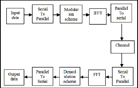
Figure 1: Block Diagram of FFT Based OFDM System |
| Therefore OFDM symbol can be expressed as |
 (1) (1) |
| Where x (n) denotes the sample of the OFDM signal, X(m) denotes the modulated symbol within subcarrier and N is the number of subcarriers. On receiver side this symbol are converted back to parallel stream and mapped with FFT then with demodulation scheme and converted to serial data as output data. |
| The demodulated symbol stream is given by |
 (2) (2) |
| Where w (m) corresponds to the FFT of the samples of the w(n) |
III.ANALYSIS OF ICI
|
| The main difficulty with OFDM, is its vulnerability to small differences in frequency at the transmitter and receiver, normally referred to as frequency offset, caused by Doppler shift due to relative motion between the transmitter and receiver, or by differences between the frequencies of the local oscillators at the transmitter and receiver |
| The received signal is given by, |
 |
 (4) (4) |
| K=0,1,.........N-1 |
| Where N is the total number of the subcarriers, X(k) denotes the transmitted symbol is an additive noise sample. S (lk) is the complex coefficients for the ICI components in the received signal. The sequence S (l-k) is defined as the ICI coefficient between and subcarriers, which can be expressed as |
 (5) (5) |
| The first term in the right-hand side of (4) represents the desired signal. The second term is the ICI components. To analyse the effect of ICI on the received signal, we consider a system with N=32 carriers. The frequency offset values used are 0.4 and 0.8,The complex ICI coefficients S(l-k) are plotted for all sub-carrier indices in Figure 2. |
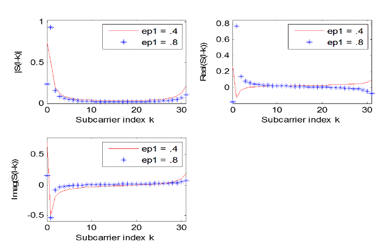
Figure 2: ICI Coefficients for N=32 Carriers |
| The figure 2 shows that for a larger ε, the weight of the desired signal component, S(0), decreases, while the weights of the ICI components increases. We can notice that the adjacent carrier has the maximum contribution to the ICI. This fact is used in the ICI self-cancellation technique. |
IV.ICI SELF CANCELLATION SCHEME
|
| ICI Cancelling Modulation |
The main concept of this scheme is to modulate the input data symbol onto a group of subcarriers with predefined coefficients such that the generated ICI signals within that group cancel each other, hence the name self- cancellation. One data symbol is not modulated in to one sub-carrier, rather at least in to two consecutive sub-carriers [8, 9, 10]. ICI Cancelling Modulation: The ICI self-cancellation scheme requires that the transmitted signals be constrained such that  , then the received signal on subcarrier k becomes , then the received signal on subcarrier k becomes |
 (6) (6) |
| Similarly the received signal on subcarrier k+1 becomes |
 (7) (7) |
| In such a case, the ICI coefficient is denoted as |
 (8) (8) |
 |
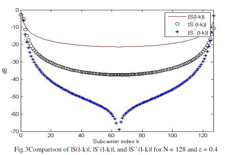 |
| ICI Cancelling Demodulation |
| ICI modulation introduces redundancy in the received signal since each pair of subcarriers transmit only one data symbol. This redundancy can be exploited to improve the system power performance, while it surely decreases the bandwidth efficiency. To take advantage of this redundancy the received signal at the (k+1)th subcarrier, where k is even, is subtracted from the subcarrier. This is expressed mathematically as |
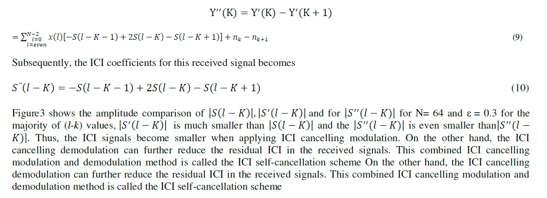 |
 |
V. CONCLUSION
|
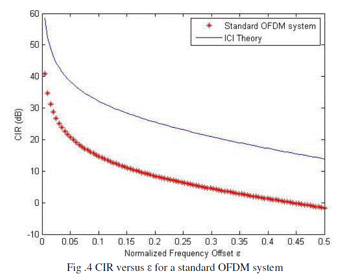
| In this paper, the performance of OFDM systems in the presence of frequency offset between the transmitter and the receiver has been analysing in terms of the CIR and the bit error rate (BER) performance. ICI which results from the frequency offset degrades the performance of the OFDM system. Here in this paper we use method of the ICI selfcancellation (SC). The self cancellation does not require very complex hardware or software for implementation. The simulations were performed in an AWGN channel. This model can be easily adapted to a flat-fading channel with perfect channel estimation. |
References
|
- Ghassan M. T. Abdalla, “Orthogonal Frequency Division Multiplexing Theory and Challenges”, UofKEJ ,Vol. 1, Issue 2, pp. 1-8, (October2011).
- T. Wang, J. G. Proakis, E. Masry, and J. R. Zeidler, “Performance Degradation of OFDM Systems Due to Doppler Spreading”,IEEETransactions on Wireless Communications, vol. 5, pp. 1422-1432, June 2006.
- R.Kumar, S.Malarvizhi, “Time Domain Equalization Technique for Intercarrier Carrier Interference Suppression in OFDM System”, InformationTechnology Journal, ANSINET, Vol 7(1), PP.149-154,1-jan-2008.
- Yin-Ray Huang1, Carrson C, “Frequency Domain Equalization for OFDM Systems with Insufficient Guard Interval using null subcarriers”,17thEuropean Signal Processing Conference (EUSIPCO 2009) Glasgow, Scotland, August 24-28, 2009.
- L.ucaRugini“BER of OFDM system impaired by carrier frequency offset in multipath fading channels”,IEEE transaction on wirelesscommunication ,vol.4.no.5,September 2005.
- B.SathishKumar,K.R.ShankarKumar,“An Efficient Inter Carrier Interference Cancellation Schemes for OFDM Systems”,(IJCSIS) InternationalJournal of Computer Science and Information Security, Vol. 6, No. 3, 2009.
- M. Palanivelan, Sheila Anand “PAPR and ICI Reduction in OFDM Systems using Modified Raised Cosine Power Pulse Shape”. EuropeanJournal of Scientific Research Vol.72, No.4 (2012), pp. 618-627.
- Srabani Mohapatra, Susmita Das,“PerformanceEnhancement of OFDM System with ICI Reduction Technique”,Proceedings of the WorldCongress on Engineering, Vol.1, July 1 - 3, 2009, London, U.K.
- Hen-GeulYeh,“A scheme for cancelling ICI transmission in multicarrier communication system,” IEEE transaction on wireless communication,vol.6,Issue.1,jnuary 2007.
- Shruti M. Kallurwar, RahilaPatel ,“An Experimental Study to Reduce the Effect of ICI in OFDM Based WLAN System”,IJCST, Vol. 3, Issue 1,Jan. - March 2012.
- Haitham J. Taha, M.F.M. Salle, “ICI Self-Cancellation for FFT-OFDM System”, Australian Journal of Basic and Applied Sciences, 4(11): 5621-5629, 2010.
- K.Prasad, K.Ramudu ,“Compensation of Inter Carrier Interference in OFDM Systems by using Self Ccancellation Scheme”, IJART, Vol. 2, Issue3, 2012.
|