Keywords
|
| chaos, non-linear, permanent-capacitor, periodicity, phase-plot |
I. INTRODUCTION
|
| The Permanent capacitor single-phase induction motors (SPCIMs) are commonly found in the drive systems of fans, compressors and pumps etc. Here in these particular modelling performance characteristics of the induction motors circuit of lumped parameters are used; offering simplicity and fast computation. Assumptions of the mathematical linearity of magnetic circuits and negligible slotting of the stator and rotor are considered. |
| Chaos can be defined as an a-periodic long term behaviour in a deterministic system that exhibits sensitive dependence on initial condition. Power systems, power converters, motor drives, telecommunications and medical electronics are few of the electrical systems that have already been identified to exhibit chaotic behaviours; characterized by a noise-like spectrum which has a continuous broad-band nature. As the initial state of a practical system can only be specified with some tolerance, the long-term behaviour of a chaotic system can never be predicted accurately. |
 |
| The paper here is sub-divided conveniently into parts. Part I. gives us the Introduction, Part II. has the D-Q axis modelling of the single-phase permanent-capacitor induction motor. The MATLAB/SIMULINK modelling of the system has been described in Part III. The results and MATLAB/SIMULINK simulations have been discussed in Part IV. Finally the conclusion is discussed in Part V. It is followed by references and bibliography. |
II. D-Q AXIS MODELING OF THE MOTOR
|
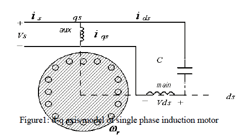
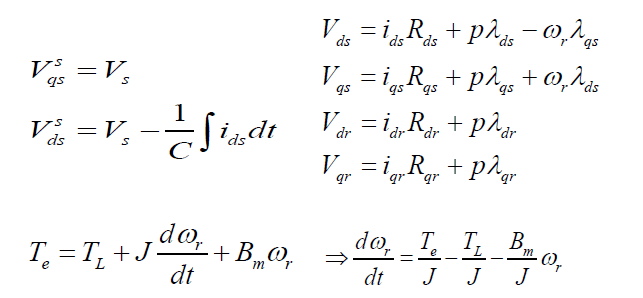
| The D-Q model a single phase induction machine can be considered to be an unsymmetrical two phase induction machine. Three-phase machines’ modelling can be easily be defined by the D-Q axis modelling. The equivalent circuit thus obtained can be represented for the SPIM is shown in alongside figure, and the machine is modelled by the following equations: |
 |
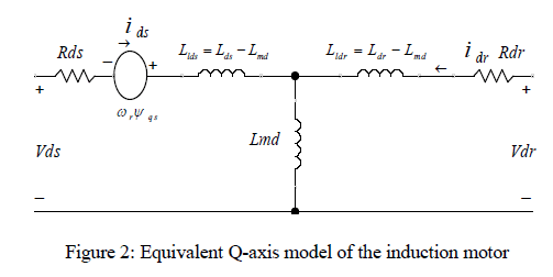 |
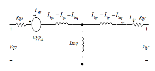
Figure 3: Equivalent D-axis model of the induction motor |
| where, |
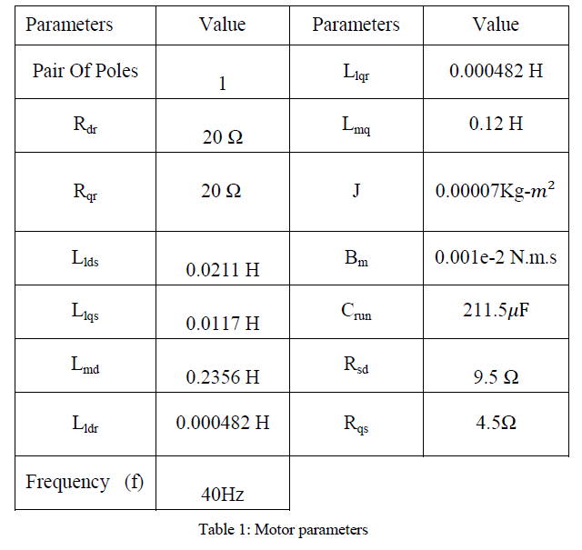
| Rdr = Direct axis rotor resistance, |
| Rqr = Q-axis rotor resistance, |
| Llds = Direct axis stator leakage inductance, |
| Llqs = Q-axis stator leakage inductance, |
| Lmd =Direct axis mutual inductance, |
| Lldr = Direct axis rotor leakage inductance, |
| Llqr = Q-axis rotor leakage inductance, |
| Lmq = Q-axis mutual inductance, |
| ωr = Rotor angular speed and |
| ω = Speed of the reference frame, |
III. MATLAB/SIMULINK MODELLING
|
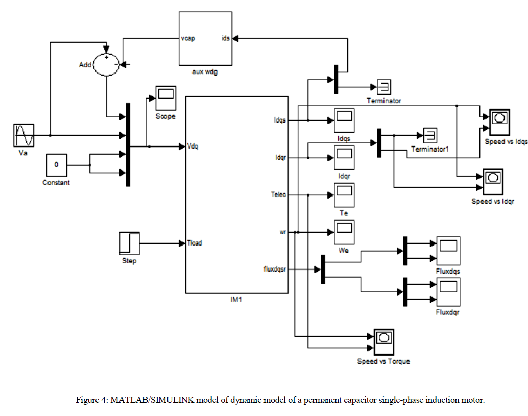
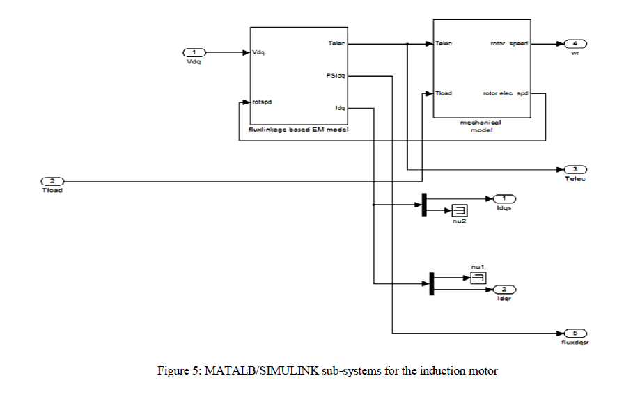
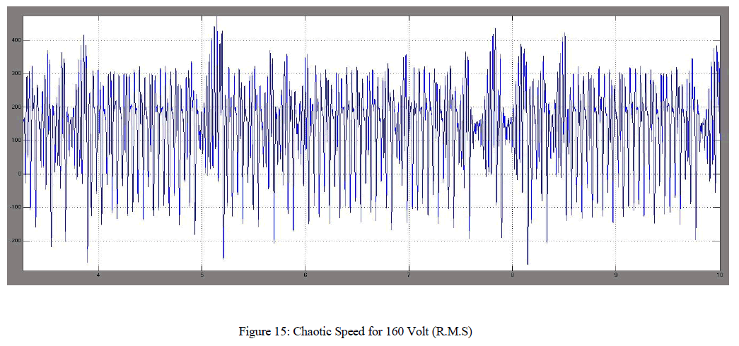
| For a system possessing more than one unique behavior, as a parameter is varied, an abrupt change in the steady-state behavior of the system is called a bifurcation. Here we vary the amplitude of applied voltage. The voltage is varied from zero to 160 volt (r.m.s). The Two (main and auxiliary) stator windings are displaced 90 degree in space. Normally the capacitor is connected with auxiliary winding and the value is selected in such a way that the auxiliary current leads the main winding current by 90 degree for balanced operation. The modeling of the single phase permanent capacitor induction motor projects the non-linear model of the system. Here to inject non linearity the capacitor is connected to the main winding instead of auxiliary winding and the inductance value of the auxiliary winding is chosen in such a way that the phase difference of currents in the two winding is very less and also different in magnitude. It can be found that the chaotic speed waveforms offer the well-known chaotic properties, namely random-like but bounded oscillations. Also, these waveforms are a-periodic and very sensitive to the initial condition. Physically, these chaotic motions reveal the unbalanced status of the interaction between the magnetic fields by the main winding and the auxiliary winding. |
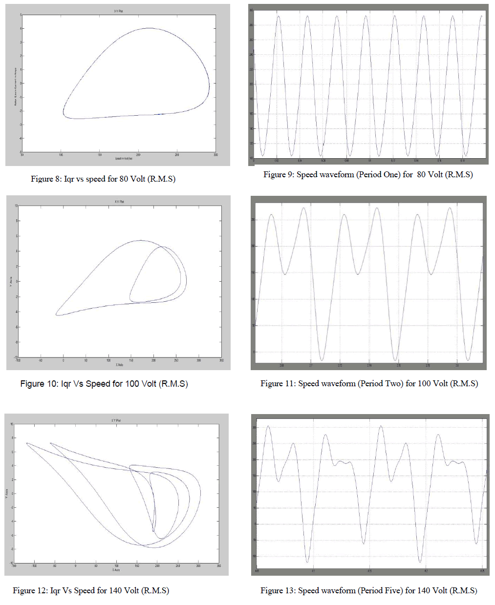
| The non-linear phenomenon in permanent capacitor single-phase induction motors (SPCIMs) are observed as the input voltage is varied from 0 to 160 Volts. Figures have shown above represents the speed waveforms and the corresponding phase-portraits, at various periodic-speed operations, namely the period-1, period-2 and period-5 operations. These waveforms consist with the well-known phenomenon of inevitable torque pulsation. It should be noted that once the operating condition are known, the motor parameter whose variation bringing chaos may be more than one. Possible candidates are the ratio of Bm to J, main winding resistance, split capacitor and so on. |
 |
 |
 |
IV. RESULTS AND SIMULATIONS
|
 |
 |
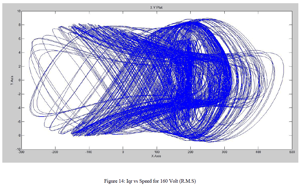 |
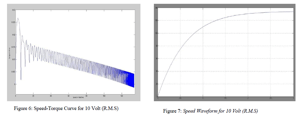
| The figures displayed above from figure 6 to figure 15 exhibits the phase-plane portrait of the system, displaying the periodicity of the permanent-capacitor motor. The phase portraits of rotor current in the quadrature-axis direction versus speed for various input voltages are plotted and the resultants are observed, determining the periodicity of the system output. The same periodicity can be observed by plotting the speed versus time graph for the corresponding voltages. The output voltages are varied from the initial r.m.s. voltage of 10volts, 80 volts (here, period one is obtained) and to a final voltage value of 160 volts (the system here enters chaos). Rotor reference frame are chosen so that the rotor variables can be closely observed and due to the chosen reference frame the induced emf due to the rotor rotation circuit is absent (ω = ωr). |
| It is to be noted that number of turns in the windings of D-axis and Q-axis are same. Hence Nd/Nq=1. As since they have different cross-sectional area, they have different values of resistances and inductances and hence the resultant inductance; all the values being referred to the stator side. |
 |
V. CONCLUSIONS
|
| The non-linear phenomenon in permanent capacitor single-phase induction motors (SPCIMs) are observed as the input voltage is varied from 0 to 160 Volts. Figures have shown above represents the speed waveforms and the corresponding phase-portraits, at various periodic-speed operations, namely the period-1, period-2 and period-5 operations. These waveforms are consistent with the well-known phenomenon of inevitable torque pulsation. It should be noted that once the operating condition are known, the motor parameter whose variation bringing chaos may be more than one. Possible candidates are the ratio of Bm to J, main winding resistance, split capacitor and so on. |
References
|
- J.H. Chen, K.T. Chau and C.C. Chan, “Analysis of chaos in current mode controlled dc drive systems,” IEEE Transactions on Industrial Electronics, vol.47, pp. 67-76, 2000.
- K.T. Chau and J.H. Chen, “Modeling, analysis and experimentation of chaos in a switched reluctance drive system,” IEEE Transactions on Circuits andSystems - I, vol. 50, pp. 712-716, 2003.
- Y. Gao and K.T. Chau, “Design of permanent magnets to avoid chaos in PM synchronous machines,” IEEE Transactions on Magnetics, vol. 39, no. 5,pp. 2995-2998, 2003.
- Gao, Y; Chau, KT; Ye, S “A novel chaotic-speed single-phase induction motor drive for cooling fans”, The 40th I A S Annual Meeting IndustryApplications Conference Record, Hong Kong, China, 2-6 October 2005, v. 2, p. 1337-1341.
- Krzysztof MakowskI, Marcin J. Wilk, Wroclaw University of Technology, Institute of Electrical Machines, Drives and Measurements “Determination ofdynamic characteristics of the single-phase capacitor induction motor” PrzeglandElektrotechniczny (Electrical Review), ISSN 0033-2097, R.87 NR5/2011
- Dynamic simulation of electric machinery usingMATLAB/SIMULINK by Chee-Mun Ong. Prentice Hall PTR 1998, ISBN 0-13-723785-5
- Analysis of Electric Machinery and Drives Systems by Paul C. Krause, Oleg Wasynczuk and Scott D. Sudhoff. Second (IEEE Press Series on PowerEngineering) 05-Mar-2002
|