ISSN ONLINE(2319-8753)PRINT(2347-6710)
ISSN ONLINE(2319-8753)PRINT(2347-6710)
A.Arulkumar1, Dr.N.RathinaPrabha*2, M.KalaRathi3
|
| Related article at Pubmed, Scholar Google |
Visit for more related articles at International Journal of Innovative Research in Science, Engineering and Technology
Instantaneous active and reactive power (p–q) control strategy is used for extracting the threephase reference currents for shunt active filters;However, in the proposed approach only calculation of real power losses are considered for extracting the three-phase reference currents for shunt active filters, evaluating their performance using a three phase, five level cascaded multilevel VSI based active filter with PI Controller in MATLAB/Simulink environment. The Real Power Theory control strategy is able to yield an adequate solution when source voltages are distorted and/or unbalanced sinusoidal. Extensive simulations are carried out with PI controller for Real Power Theory control strategy under transient and steady state conditions and adequate results are presented with different nonlinear loads.
Keywords |
| Harmonic compensation, SAF (shunt active filter), p–q control strategy, PI controller, Triangular Carrier Current Controller. |
INTRODUCTION |
| In recent years Electrical power quality [1] becomes an important and growing problem because of the proliferation of nonlinear loads such as power electronic converters in typical power distribution systems. Particularly, voltage harmonics and power distribution equipment problems result from current harmonics produced by nonlinear loads. Harmonics surfaced as a buzz word from 1980s which always threaten the normal operation of power system and user equipment. Highly automatic electric equipments, in particular, cause enormous economic loss every year. Owing both power suppliers and power consumers are concerned about the power quality problems and compensation techniques. |
| It is noted that non-sinusoidal current results in many problems for the utility power supply company, such as: low power factor, low energy efficiency, electromagnetic interference (EMI), distortion of line voltage, etc. It is renowned that when neutral wire is overheated then excessive harmonic current will pass through the neutral line, which is three times that of zero sequence current. Thus a perfect compensator is necessary to avoid the consequences due to harmonics. Though several control techniques and strategies [7] have been developed but still performance of filter in contradictions, this gives primary motivation for the proposed approach. Instantaneous active and reactive theory (p–q theory) was introduced by Akagi, Kawakawa, and Nabae in 1984[1]. Since then, many scientists[6-7]and engineers made significant contributions to its modifications in three-phase four-wire circuits and its applications to power electronic equipment. The p–q theory [6] based on a set of instantaneous powers defined in the time domain. No restrictions are imposed on the voltage and current waveforms, and it can be applied to three phase systems with or without neutral wire for three phase generic voltage and current waveforms. Thus it is valid not only in the steady state but also in the transient state. This paper presents an instantaneous real-power compensator based cascaded shunt active power filter for the harmonics and reactive power elimination. The cascaded H- Bridge multilevel VSI has been applied for active filter applications due to increased number of voltage levels, low switching losses and higher order of harmonic compensation. The cascaded M-level inverter consists of (M-1)/2 H-bridges and each bridge have its own separate dc source [1]. The cascaded multilevel voltage source inverter switching signals are generated using proposed triangular carrier current controller; it provides a dynamic performance under transient and steady state operating conditions. The compensation process involves calculation of real-power (p) losses only that is derived from sensing phase voltages and distorted source currents. The PI-controller is used to maintain the capacitance voltage of the cascaded inverter constant. The shunt APF system is validated through extensive simulation and investigated under steady state and transient conditions with different non-linear loads. |
II. PROPOSED INSTANTANEOUS REAL POWER THEORY |
| In this method [7], a set of voltages vsa, vsb, vsc and currents from phase coordinates are first transferred to the αβ coordinates using Clark transformation as |
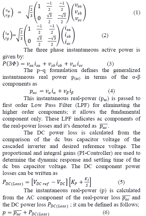 |
| The instantaneous current on the α-β coordinates of are divided into two kinds of instantaneous current components; first is real-power losses and second is reactive-power losses, but this proposed controller computes only the real-power losses. So the α-βcoordinate currents , are calculated from the vα and vβ voltages with instantaneous real-power p only and the reactive power q is assumed to be zero. This approach reduces the calculations and shows better performance than the conventional methods. The α—β coordinate currents can be calculated as |
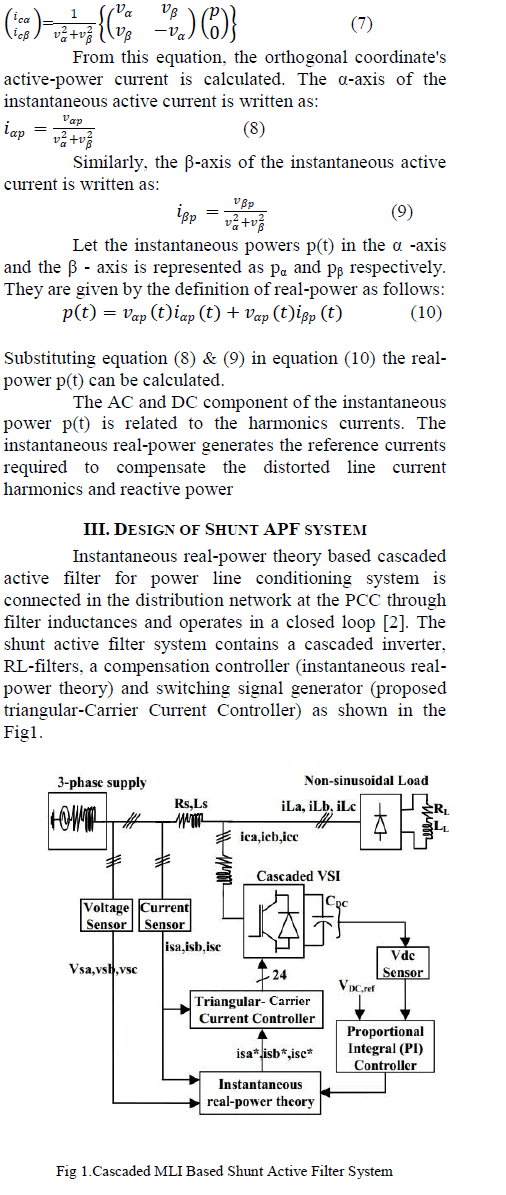 |
| The three-phase source is connected with nonlinear load and this nonlinear load current contains fundamental and harmonic components. If the active power filter provides the total reactive and harmonic power, will be in phase with the utility voltage and would be sinusoidal. At this time, the active filter must provide the compensation current; )(11) Therefore, active power filter estimates the fundamental components and compensating the harmonic current and reactive power. A. Power Converter A cascaded multilevel active power inverter is constructed by the conventional H-bridges. The threephase active filter comprises of 24-power transistors with diodes and each phase consists of two-H-bridges in cascade method for 5-level output voltage, shown in Fig 2. |
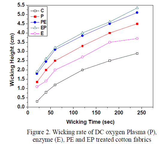 |
| Each H-bridge is connected to a separate dc-bus capacitor and it serves as energy storage elements to supply the real-power difference between load and source during the transient period [16-171. The capacitor voltage is maintained constant using PI-controller. The 24- power transistors switching operations are performed using triangular carrier current controller and harmonics is achieved by injecting equal but opposite current harmonic components at Point of Common Coupling. B. Reference Current Control strategy The control scheme of the shunt active power filter must calculate the current reference signals from each phase of the inverter using instantaneous real-power compensator. The block diagram as shown in Fig.3, that control scheme generates the reference current required to compensate the load current harmonics and reactive power. The P1- controller maintains the dc-bus voltage across the capacitor as constant. The instantaneous real power compensator with PI-controller is used to extract reference value of current to be compensated |
 |
| The compensator reference currents in abc domain is calculated from the inverse Clarke transformation and it can be written as |
 |
| C. DC Link voltage regulation For regulating and maintaining the DC link capacitor voltage [12], the active power flowing into the active filter needs to be controlled. If the active power flowing into the filter can be controlled equal to the losses inside the filter, the DC link voltage can be maintained at the desired value. The quality and performance of the SAF depends mainly on the method implemented to generate the compensating reference currents. This paper presents a p-q method to get the reference current, which is key issue in the control of the SAF. In order to maintain DC link voltage constant and to generate the compensating reference currents a PI controller is used. The actual capacitor voltage is compared with a set of reference value. The error signal is then processed through a PI controller. The output of the PI controller is considered as real power loss component of APF that is nothing but the power flow needed in to DC side of the inverter, to maintain the average capacitor voltage constant. It compensates conduction losses and switching losses. Proportional Integral controller is used in order to eliminate the steady state error and reduce the ripple voltage of the cascaded inverter. The transfer function is defined as |
| The proportional and integral gains[KP =0.7,KI =1]are set in such a way that actual Vdcacross capacitor is equal to the reference value of Vdc voltage. D. Triangular Carrier Current Controller The triangular carrier current controller is one of the familiar methods for active power filter applications to generate gate control switching pulses of the voltage source inverter. To determine the switching transitions by means the error current [desired reference current (Isa*) compared with the actual source current (Isa)] is multiplied with proportional gain (Kp). The output signal of the proportional gain is compared with triangular carrier signal. |
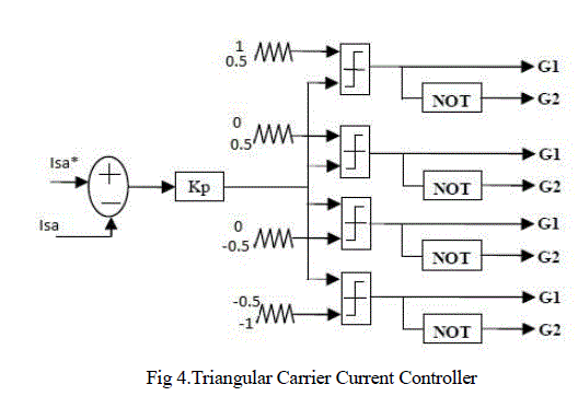 |
| The four triangular signals are generated that is having same frequency with different amplitude for cascaded multilevel inverter to avoid overlapping of one converter with other phase. Thus the switching frequency of the power transistor is equal to the frequency of the triangular-carrier signals. |
IV. RESULT AND ANALYSIS |
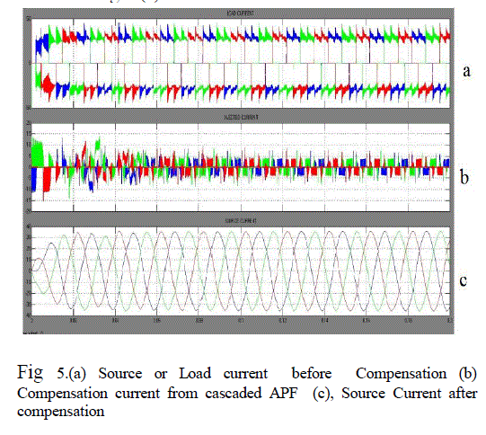
| The performance of the PI controller based cascaded active power filter is evaluated through extensive simulation using MATLAB /Sim power tools in order to model and test the system. The system source is chosen as 440 V, 50 Hz .For nonlinear load a diode rectifier with a RL load is chosen. DC side capacitance (Cdc) with various reference voltage (VDC ref) has been taken into consideration as energy storage element. Power devices used are IGBTs with diodes. Simulation of the three phase diode rectifier with filter capacitor, load current or source current before compensation are shown in Fig 5.(a). This indicates the load current contains the fundamental and harmonic components.The equal and opposite magnitude of harmonic current is injected at PCC is shown in Fig 5.(b). The three-phase source current after compensation is shown in Fig 5.(c) in which the current is sinusoidal. |
 |
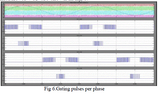
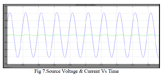
| For the purpose of harmonic reduction and power factor correction the switching pulses to the switches of shunt active filter is produced by using triangular carrier current controller and the generated switching pulses for a single phase five level cascaded multilevel VSI are shown in fig.6.In addition to this, power factor correction was also achieved as shown in Fig.7.The result indicates phase-A voltage is in-phase with phase-A current. This Figure illustrates for single phase only where as the remaining two phases are similar but shifted by 1200. |
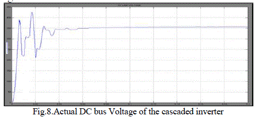
| Using PI controller the dc-side capacitor voltage reaches its steady state after 2 cycles and is shown in Fig.8. |
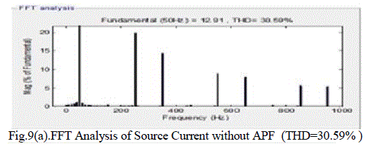
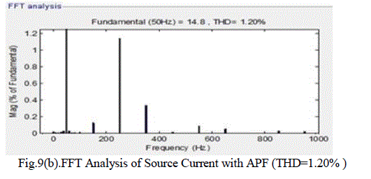
| The Fast Fourier Transform (FFT) is used for analyzing the harmonic content and is done with the fundamental frequency 50 Hz. THD of source current without and with using Active Power Filter is shown in Fig 9.(a) and 9.(b). |
 |
 |
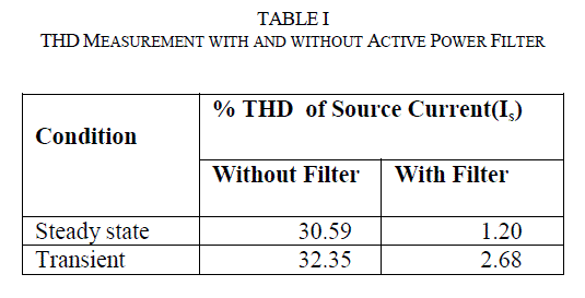
| The Total Harmonic Distortion (THD) is measured under both steady state and transient conditions and they are presented in Table I .From this table, it is obvious that the PI Controller response is better during Steady State Condition |
 |
 |
 |
 |
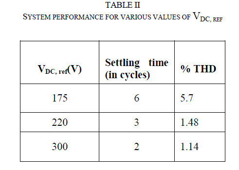
| The system performance for various values of VDCref under similar load conditions is shown in Table II. From this Table II it is also clear when VDCrefis high, the settling time and THD are found to be low. |
 |
CONCLUSION |
| The instantaneous real power theory based shunt active power filter has been proposed to improve the power quality by compensating harmonics and reactive power requirement of the nonlinear load. The performance of a Real Power Theory based shunt active power filter has been studied with the conventional PI Controller. From the simulation results it is obvious that the compensation process is simple, and is based on sensing Phase voltages and Phase currents only. The PI controller has a better steady state response. The THD of the source current after Compensation is well below 5%, the harmonic limit imposed by the IEEE-519 standard. For Levels higher than three, there is the problem of maintaining individual capacitor voltage balance due to un symmetrical loading of capacitor. This problem can be eliminated by Swapping of Pulses. |
References |
|