ISSN ONLINE(2319-8753)PRINT(2347-6710)
ISSN ONLINE(2319-8753)PRINT(2347-6710)
| Punemsujith chandra, S.C.Gupta Department of Electrical Engineering, MANIT, Bhopal, India2 |
| Related article at Pubmed, Scholar Google |
Visit for more related articles at International Journal of Innovative Research in Science, Engineering and Technology
This paper introduces a power control strategy of a grid connected hybrid system. And this hybrid system is a combination of a photovoltaic generator (PVG) and a fuel cell (FC).PVG is associated with a boost converter with a maximum power point method (MPPT). And FC is connected with a boost converter. To control the power delivered by the systems, an hysteresis control is used. A 7.2 KW hybrid inverter and its control system is developed. The proposed model is simulated through MATLAB/SIMULINK and their results are presented in this paper.
Keywords |
| Photovoltaic generator (PVG), Fuel cell (FC),Maximum power point technique (MPPT). |
INTRODUCTION |
| The integration of renewable energy sources and energy-storage systems has been one of the new trends in power-electronic technology. The increasing number of renewable energy sources and distributed generators requires new strategies for their operations in order to maintain or improve the power-supply stability and quality. Combining multiple renewable resources via a common dc bus of a power converter has been prevalent because of convenience in integrated monitoring and control and consistency in the structure of controllers as compared with a common ac type. |
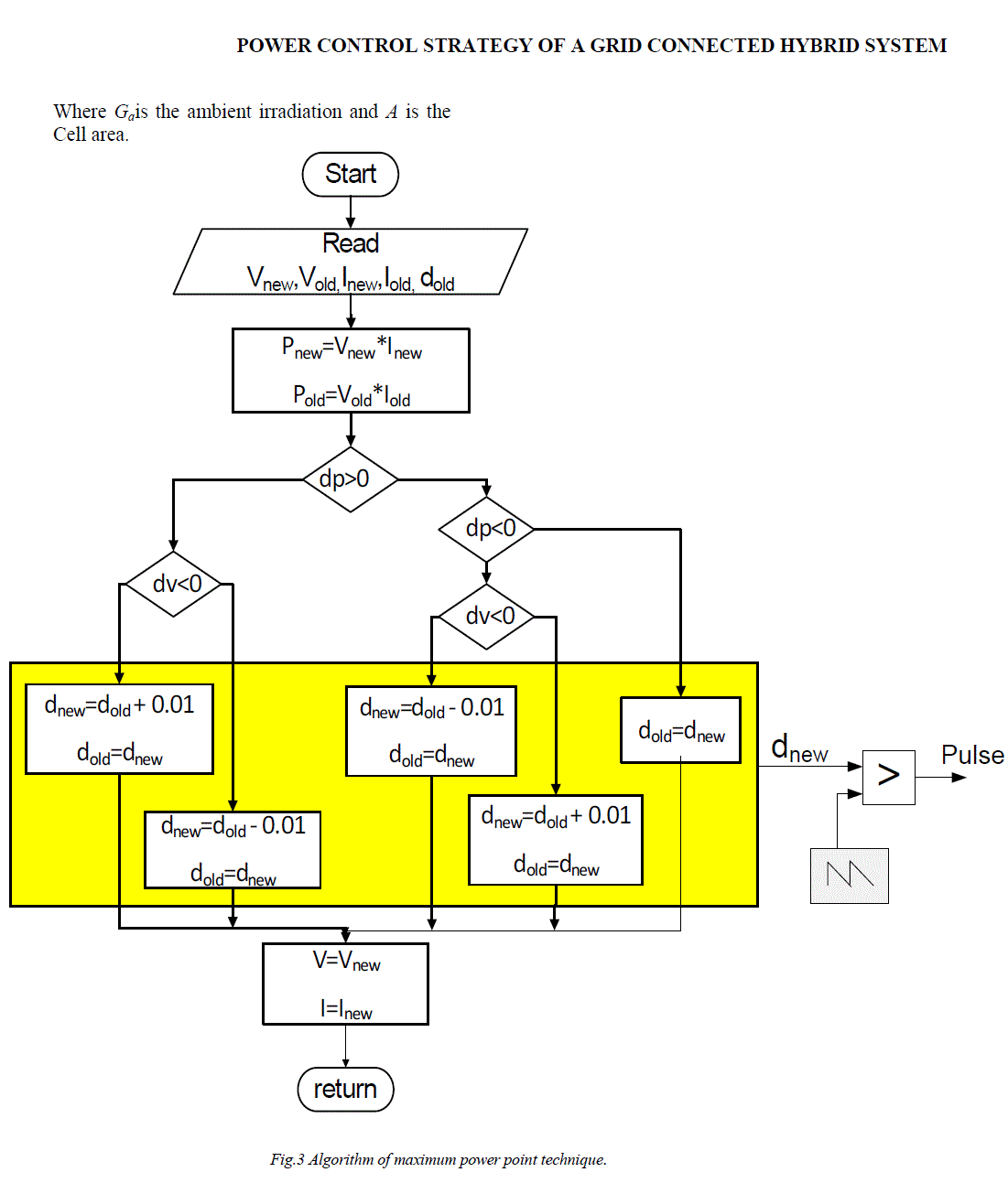
| Solar energy is one of the most important renewable energy sources. As opposed to conventional unrenewable resources such as gasoline, coal, etc., solar energy is clean, inexhaustible and free. Unfortunately, PV generation systems have two major problems: the conversion efficiency of electric power generation is very low (9-17%), especially under low irradiation conditions and the amount of electric power generated by solar arrays changes continuously with weather conditions. Moreover, the solar cell V-I characteristic is nonlinear and varies with irradiation and temperature. In general, there is a unique point on the V-I or V-P curve, called the Maximum Power Point (MPP), at which the entire PV system (array, converter, etc.) operates with maximum efficiency and produces its maximum output power. The location of the MPP is not known, but can be located, either through calculation models or by search algorithms. Therefore Maximum Power Point Tracking (MPPT) techniques are needed to maintain the PV array’s operating point at its MPP. Fuel cell is an electrochemical device that converts oxygen and hydrogen to electrical power with water as the only by product. Fuel cell based power systems are considered as one of the most promising and clean energy sources. Fuel cell systems are truly heterogeneous systems involving mechanical, chemical, thermal and electrical systems. This makes system level modelling a significant challenge that very few modelling tools can handle. The challenges consist of both numerical issues and model configuration management issues. In this paper the modelling of this fuel cell is also done. Both the photovoltaic and fuel cell models are integrated in a hybrid system. The control of this grid connected hybrid system is discussed and their simulation results are presented in this paper. |
II. SYSTEM CON FIGURATION |
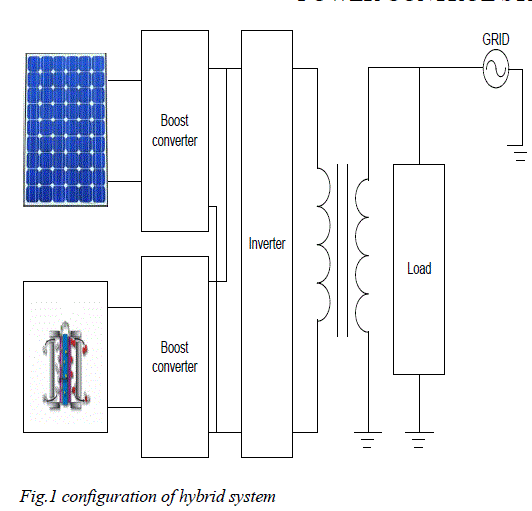
| The fig.1 shows the configuration of the proposed hybrid system. This hybrid system consists of a PV generator and a Fuel cell. The PV generator system consists of a PV array modelling and a boost converter to boost the voltage to a higher level. And also an MPPT method is used to track maximum power. The fuel cell also consists of its modelling and a boost converter. Both these systems are connected in parallel and are connected to an inverter. The inverter is controlled based on the hysteresis control to the inverter other end a transformer is connected. And to the transformer grid and local loads are connected. |
 |
III. PV GENERATOR |
| A PV generator is assembly of solar cells, connections, protective parts, supports etc. In the present modelling, the focus is only on cell/module/array. A p-n junction diode fabricated in a thin wafer or layer of semiconductor generally silicon is present inside the solar cell. In the dark, the output characteristic of a solar cell (I-V characteristics) has an exponential characteristic similar to that of a diode. When photons hits the solar cell, with greater than band gap energy of the semiconductor, electrons are knocked loose from the atoms creating electron-hole pairs. These carriers are swept apart under the influence of the internal electric fields of the p-n junction and create a current proportional to the incident radiation. When the cell is short circuited, this current flows in the external circuit; when open circuited, this current is shunted internally by the intrinsic p-n junction diode. The characteristics of this diode therefore set the open circuit voltage characteristics of the cell. |
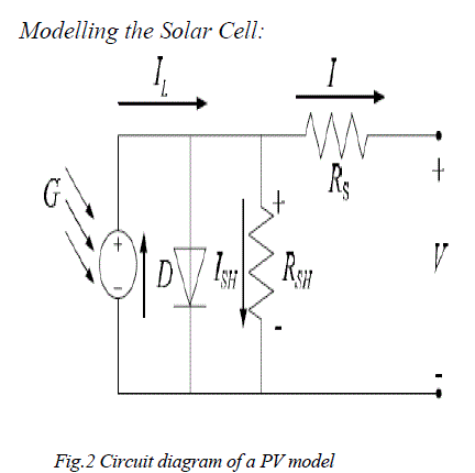 |
| current source is directly proportional to the light falling on the cell (photocurrent Iph). In the absence of sunlight it neither produces current nor a voltage. However, a dark current or diode current is generated when it is connected to a external supply(large voltage). The diode determines the I-V characteristics of the cell. Increasing sophistication, accuracy and complexity can be introduced to the model by adding in turn. |
| ïÃâ÷ Temperature dependence of the : Photo current IL. Diode saturation current I0. ïÃâ÷ A series resistance Rs, which represents the internal losses due to the current flow and also gives a accurate shape between the maximum power point and the open circuit voltage. ïÃâ÷ A resistance in parallel with the diode, which corresponds to the leakage current to the ground Shunt resistance Rsh. ïÃâ÷ In an ideal cell Rs = Rsh = 0, which is a relatively common assumption. In our paper, a model of moderate complexity was used. Assumed that the net current of the cell is the difference of the photocurrent, IL and the normal diode current I0. |
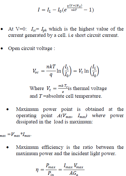 |
| Where Gais the ambient irradiation and A is the Cell area. |
 |
IV. FUEL CELL |
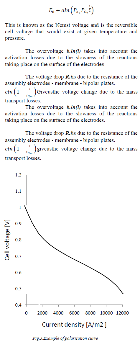
| The FC system converts the hydrogen into electrical energy. The core of the FC consists of two electrodes, the anode and the cathode, separated by a membrane electrolyte. The most common way to characterise the performances of the FC is the static polarisation curve. The main parameters which affect the FC performances are the membrane and electrode characteristics, the cell design, the operating pressure, temperature and purity of the gases. Figure 4 shows such a polarisation curve (voltage of the cell versus current density). The shape is due to four major irreversibility’s: activation losses, fuel crossover and internal currents, ohmic losses in the electrodes and in the membrane, mass transport or concentration losses. The polarisation curve shown in fig.3 iscomputed, and it is known as Tafel equation: |
 |
| This equation takes into account the temperatures, the pressures of oxygen and hydrogen as well as the current going through the FC. |
| Eois the cell EMF at standard pressure. |
 ` ` |
| The voltage of a single cell is quite small. This means that to produce enough voltage, several cells have to be connected in series to create a stack. Furthermore the FC stack cannot operate alone: air and fuel will need to be circulated through the stack using. Pumps, fans, a compressor, etc. These devices are known as auxiliaries or parasitic. Their power consumption has to be taken into account in the calculation of the FC system efficiency. The auxiliaries can be connected to the DC bus or to the grid. We will only consider the second case in this paper. The simulation of the FC system as well as the simulations of the other power supply subsystems is made in the MATLAB/SIMULINK environment. The maximal power of the FC stack is 330kW. Its voltage output varies between 600V (no load) and 300V. |
| Boost converters: |
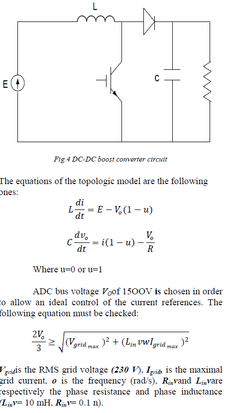
| ADC-DC boost converter is used to realise the voltage adaptation between the FC output E and the DC bus Vo. |
 |
V. CONTROL STRATEGY |
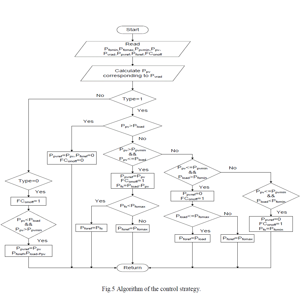
| Here we are having two modes of operation based on the load power required. The algorithm is shown in fig.5 the two modes can be selected manually in which fuel cell is always on irrespective of the load condition. In the second mode fuel cell may or may not be switched on based on the load power required. If the load power required is more than the power generated by the PV generator then the excess power is generated by the fuel cell. If the power required by the load is very much less than the threshold power of the PV generator (the minimum power generation limit of pv generator), then it will switch on the fuel cell and its power is utilised by the load. The complete control strategy is given below in fig.5 algorithm |
 |
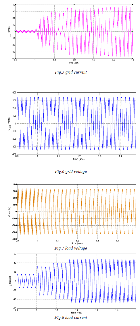
VI. SIMULATION RESULTS: |
 |
VII. CONCLUSION |
| In this paper power control strategy for versatile power transfer for a grid-connected PV/FC hybrid system has been proposed. Two modes of operations were added for flexible operation and improvement in quality of power delivered to the grid. A hysteresis control was applied to control the power delivered to the local load and the grid. The proposed control offers grid or user a friendly option in operating modes. Simulation results provided various dynamic characteristics of the proposed control scheme, which enabled comprehensive quantitative and qualitative analysis before a real hardware implementation. |
References |
|