ISSN ONLINE(2319-8753)PRINT(2347-6710)
ISSN ONLINE(2319-8753)PRINT(2347-6710)
Prabaharan R1 ,Jayaramaprakash A1 , VijayAnand L2
|
| Related article at Pubmed, Scholar Google |
Visit for more related articles at International Journal of Innovative Research in Science, Engineering and Technology
In this paper , some of the shortcomings in the existing system has been proposed to be rectified. The advances have allowed numerous ways for power harvesting systems in practical applications in order to meet the power demand. The use of piezoelectric crystal is to generate electric output from surrounding vibrations . Piezoelectric materials have a crystalline structure that they can convert mechanical energy into electrical charge and is vice-versa. These materials have the ability to absorb mechanical energy from their surroundings, usually ambient vibration, and transform it into electrical energy that can be used to power other devices. The produced electrical energy from the piezoelectric crystal is very low in the order of 2-3volts and is initially stored in a 2v rechargeable battery through a charge controller ,since it is not possible to charge a 12V battery through crystal output . In order to increase the voltage, the boost converter circuit is used. The use of boost converter is to increase the level of voltage ranges about 12V and is stored in a 12V battery. In order to supply power to the load an inverter circuit is required by which the generated voltage is fed to the CFL lamp load .This project can be implemented in dense populated areas like railway station ,bus stands etc where more amount of vibration energy will be obtained. In this paper, we discuss about many researches that has been performed in the area of power harvesting.
Keywords |
| Power harvesting, Energy generation, Piezoelectric crystal |
INTRODUCTION |
| Man has needed and used energy at an increasing rate for his purpose. Due to this a lot of energy resources have been exhausted and wasted. The utilization of waste energy of foot power with human locomotion is very much relevant for highly populated countries where the roads, railway stations, bus stands, temples, etc. The human bio-energy being wasted if it can be made possible for utilization it will be very useful energy sources. Walking is the most common activity in day to day life. While walking, the person loses energy to the surface in the form of vibration. This energy can be tapped and converted to electrical form. In this paper, piezoelectric crystals were used as a medium. These piezoelectric crystals convert the mechanical vibrations into electrical energy. |
II. PIEZOELECTRIC CRYSTALS |
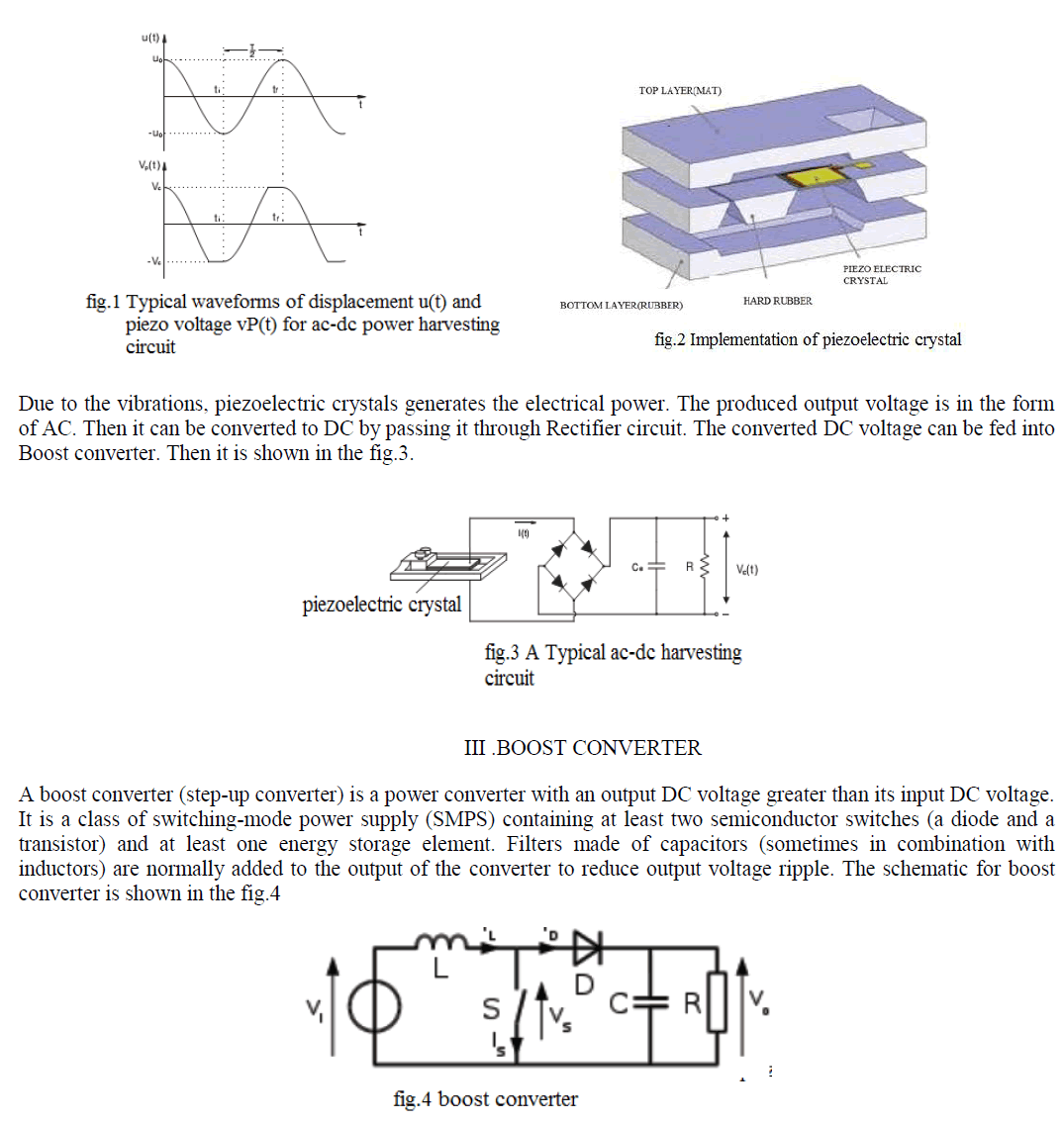
| One of the most suitable method for obtaining the energy surrounding a system is achieved by using piezoelectric crystals. Piezoelectric crystals is one of small scale energy sources. The piezoelectric crystals are subjected to vibration they generate a very small voltage, commonly known as piezoelectricity. It has a crystalline structure that converts an applied vibration into an electrical energy .The piezoelectric effect exists in two properties: The first is the direct piezoelectric effect that describes the materialâÃâ¬ÃŸs ability to transform mechanical strain into electrical charge. The second form is the converse effect, which is the ability to convert an applied electrical potential into mechanical strain energy. These properties allows the material to function as a power harvesting medium. |
 |
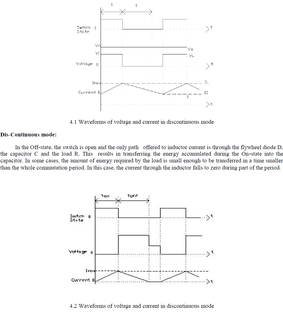
| The basic principle of a Boost converter consists of two Modes of operations: Continuous mode In the On-state, the switch S (see fig.4) is closed , resulting in an increase in the inductor current. When a boost converter operates in continuous mode, the current through the inductor (IL) never falls to zero. Figure 4.1shows the typical waveforms of currents and voltages in a converter operating in this mode. |
 |
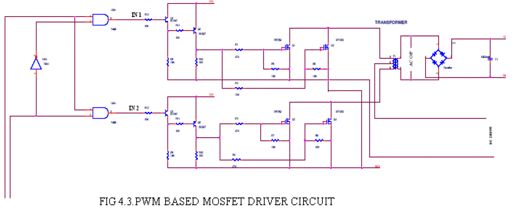
IV.PWM BASED MOSFET DRIVER CIRCUIT |
 |
PWM |
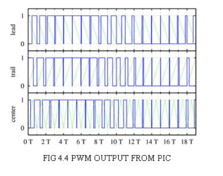
| Pulse-width modulation (PWM) of a signal or power source involves the modulation of its duty cycle, to either convey information over a communications channel or control the amount of power sent to a load. Power delivery PWM can be used to reduce the total amount of power delivered to a load without losses normally incurred when a power source is limited by resistive means. This is because the average power delivered is proportional to the modulation duty cycle. With a sufficiently high modulation rate, passive electronic filters can be used to smooth the pulse train and recover an average analog waveform. High frequency PWM power control systems are easily realisable with semiconductor switches. The discrete on/off states of the modulation are used to control the state of the switch(es) which correspondingly control the voltage across or current through the load. The major advantage of this system is the switches are either off and not conducting any current, or on and have (ideally) no voltage drop across them. The product of the current and the voltage at any given time defines the power dissipated by the switch, thus (ideally) no power is dissipated by the switch. Reallistically, semiconductor switches such as MOSFETs or BJTs are non-ideal switches, but high efficiency controllers can still be built. |
 |
| PWM is also often used to control the supply of electrical power to another device such as in speed control of electric motors, volume control of Class D audio amplifiers or brightness control of light sources and many other power electronics applications. For example, light dimmers for home use employ a specific type of PWM control. Home use light dimmers typically include electronic circuitry which suppresses current flow during defined portions of each cycle of the AC line voltage. Adjusting the brightness of light emitted by a light source is then merely a matter of setting at what voltage (or phase) in the AC cycle the dimmer begins to provide electrical current to the light source (e.g. by using an electronic switch such as a triac). In this case the PWM duty cycle is defined by the frequency of the AC line voltage (50 Hz or 60 Hz depending on the country). These rather simple types of dimmers can be effectively used with inert (or relatively slow reacting) light sources such as incandescent lamps, for example, for which the additional modulation in supplied electrical energy which is caused by the dimmer causes only negligible additional fluctuations in the emitted light. Some other types of light sources such as light-emitting diodes (LEDs), however, turn on and off extremely rapidly and would perceivably flicker if supplied with low frequency drive voltages. Perceivable flicker effects from such rapid response light sources can be reduced by increasing the PWM frequency. If the light fluctuations are sufficiently rapid, the human visual system can no longer resolve them and the eye perceives the time average intensity without flicker. |
Voltage Regulation |
| PWM is also used in efficient voltage regulators. By switching voltage to the load with the appropriate duty cycle, the output will approximate a voltage at the desired level. The switching noise is usually filtered with an inductor and a capacitor. One method measures the output voltage. When it is lower than the desired voltage, it turns on the switch. When the output voltage is above the desired voltage, it turns off the switch. |
PERIPHERAL INTERFACE CONTROLLER(PIC) |
| The microcontroller that has been used for this paper is from PIC series. PIC microcontroller is the first RISC based microcontroller fabricated in CMOS (complimentary metal oxide semiconductor) that uses separate bus for instruction and data allowing simultaneous access of program and data memory. The main advantage of CMOS and RISC combination is low power consumption resulting in a very small chip size with a small pin count. The main advantage of CMOS is that it has immunity to noise than other fabrication techniques. |
| Various microcontrollers offer different kinds of memories. EEPROM, EPROM, FLASH etc. are some of the memories of which FLASH is the most recently developed. Technology that is used in pic16F877(shown in fig 4.5)is flash technology, so that data is retained even when the power is switched off. Easy Programming and Erasing are other features of PIC 16F877.The PIC microcontroller is used here in order to generate the PWM required for the MOSFET driver circuit. |
POWER SUPPLY |
 |
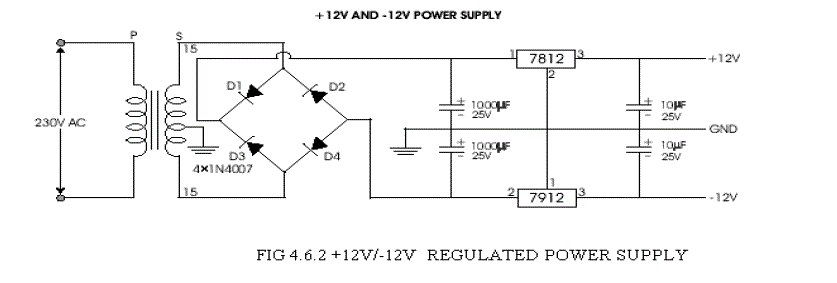
| The power supply required for the microcontroller is obtained from the source and is regulated to +5V (shown in fig4.6.1)for the proper functioning of the microcontroller. this is achieved by means of using a regulator IC 7805.Similarly another voltage regulator IC is also necessary inorder to regulate the boosted voltage to +12V(shown in fig4.6.2) which is the appropriate battery voltage. |
 |
IC voltage regulators |
| Voltage regulators comprise a class of widely used ICs. Regulator IC units contain the circuitry for reference source, comparator amplifier, control device, and overload protection all in a single IC. IC units provide regulation of either a fixed positive voltage, a fixed negative voltage, or an adjustably set voltage. The regulators can be selected for operation with load currents from hundreds of milli amperes to tens of amperes, corresponding to power ratings from milli watts to tens of watts.A fixed three-terminal voltage regulator has an unregulated dc input voltage, Vi, applied to one input terminal, a regulated dc output voltage, Vo, from a second terminal, with the third terminal connected to ground.The series 78 regulators provide fixed positive regulated voltages from 5 to 24 volts. Similarly, the series 79 regulators provide fixed negative regulated voltages from 5 to 24 volts |
Inverter |
 |
Circuit Diagram Description |
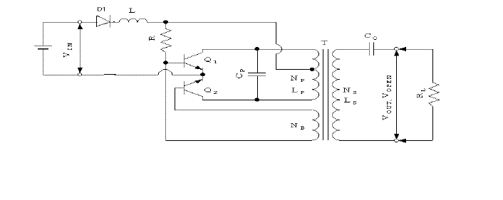
| An AC load can be powered from a DC source by using a converter to change DC to AC. This circuit is designed for taking 230V AC from the 12V DC input(shown in fig 4.7). An AC load can be powered from a DC source by using a converter to change DC to AC. This is efficiently done through above circuit with the use of two transistors Q1 & Q2 and one Transformer (T). The wattage of output depends on these three equipments. A DC-to-AC inverter energized from a 12-volt DC input signal uses a single stage inverter circuit to produce a quasi-sine wave output signal. When we are giving 12v DC input to the circuit, initially it goes to diode D1 which is used to product reverse voltage. Then Q1 will conduct first, at that time we can get the positive cycle of 230v output in the output transformer side. It will prolong some seconds and gets saturated then Q2 will conduct this time. This switching makes the reverse polarity in the output side with constant 230v output. Then Q2 will conduct some seconds and gets saturated and Q1 will conduct. Likewise this switching makes alternating 230v output in the transformer output side. This will continue up to the input given to the circuit, which makes constant 230V AC output in the transformer side. The output voltage of the inverter is decided only in the transformer. While saying in briefly, DC to AC converters a direct current voltage is applied to a so-called half bridge with two power transistors connected in series. The power transistors are gated alternatively conducting and generate at their connection point an alternating voltage for the load. DC-to-AC voltage converters have many uses, such as the supply of power to gas discharge lamps or, after rectifying and smoothing the AC voltage, supplying power to electronic circuits, motors, relays, magnetic valves, magnetic clutches, etc. DC-to-AC power converters are often used in uninterruptible power supplies. |
V. BATTERY |
NICKEL CADMIUM BATTERY |
| The nickel–cadmium battery (NiCd battery or NiCad battery) is a type of rechargeable battery using nickel oxide hydroxide and metallic cadmium as electrodes. The abbreviation Ni-Cd is derived from the chemical symbols of nickel (Ni) and cadmium (Cd): the abbreviation NiCad is a registered trademark of SAFT Corporation, although this brand name is commonly used to describe all Ni–Cd batteries.Wet-cell nickel-cadmium batteries were invented in 1898.A Ni- Cd battery has a terminal voltage during discharge of around 1.2 volts which decreases little until nearly the end of discharge. Ni-Cd batteries are made in a wide range of sizes and capacities, from portable sealed types interchangeable with carbon-zinc dry cells, to large ventilated cells used for standby power and motive power. Compared with other types of rechargeable cells they offer good cycle life and capacity, good performance at low temperatures, and work well at high discharge rates (using the cell capacity in one hour or less). However, the materials are more costly than types such as the lead acid battery, and the cells have higher self discharge rates than some other types. Sealed Ni-Cd batteries require no maintenance. Sealed Ni-Cd cells were at one time widely used in portable power tools, photography equipment, flashlights, emergency lighting, and portable electronic devices. The superior capacity of the Nickel-metal hydride batteries, and more recently their lower cost, has largely supplanted their use. Further, the environmental impact of the disposal of the heavy metal cadmium has contributed considerably to the reduction in their use. Within the European Union, they can now only be supplied for replacement purposes although they can be supplied for certain specified types of new equipment such as medical devices. Larger ventilated wet cell Ni-Cd batteries are used in emergency lighting, standby power, and uninterruptible power supplies and other applications. |
Lithium- Ion Battery |
| Pure lithium is very reactive. It reacts vigorously with water to form lithium hydroxide and hydrogen gas. Thus, a non-aqueous electrolyte is typically used, and a sealed container rigidly excludes water from the battery pack .Lithium ion batteries are more expensive than Ni Cd batteries but operate over a wider temperature range with higher energy densities, while being smaller and lighter. They are fragile and so need a protective circuit to limit peak voltages. |
V.CONCLUSION |
| The objective of this paper is to harvest the energy in the most feasible way by means of green sources. By continuously stressing the crystal for three hours the voltage developed is enough to charge a mobile battery. By introducing prieto battery ,a rechargeable battery made of nanotechnology have improve the efficiency of this system. The boost converter improves the voltage effectively and power have improved by enhancing the current gain. |
References |
|