Keywords
|
| Voltage Source Inverter, Pulse Width Modulation, Active power filter, Synchronous Reference Frame Transformation, Space Vector Modulation. |
INTRODUCTION
|
| In Variable Speed application, Voltage Source Inverter is commonly used to supply a variable frequency variable voltage to a three phase induction motor. In this PWM drives are more efficient and typically provide higher levels of performance. A suitable Pulse Width Modulation technique is employed to obtain the required output voltage of the inverter. The most common AC drives today are based on sinusoidal pulse-width modulation SPWM. . Induction motor is rugged, reliable, and single-fed machine; it can directly absorb the reactive power from the utility With this device, we can get two advantages: one is that we can get a low start current; the other is that we can change the motor speed conveniently by controlling the output frequency of the ASD. |
| Two basic types of inverters are exist in general. Current source inverter (CSI), employing a dc link inductance across the inverter and this provides a switched current waveform at the motor output terminals. CSI are robust in operation and reliable due to the insensitivity to short circuits and noisy environment. Voltage Source Inverter (VSI), employing a dc link capacitor and providing a switched voltage waveform and they are commonly used when compared to Current Source Inverter since the use of Pulse Width Modulation (PWM) in them allows efficient and smooth operation, which is free from torque pulsations and cogging. Furthermore, the frequency range of VSI is higher and they are usually more in expensive when compared to CSI drives of the same rating. Both Voltage Source Inverters and Current Source Inverters are used in adjustable speed AC drives. However, Voltage Source Inverters with constant Volts/Hertz (V/f) are more popular, where the need of high accuracy of speed control is not crucial and for the applications without position control requirements. |
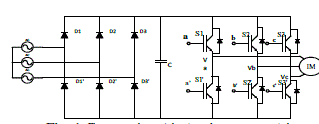 |
| Fig. 1 Conventional induction motor drive |
| Sinusoidal Pulse Width Modulation technique is applied to Voltage Source Inverter, In sinusoidal PWM instead of maintaining the width of all pulses the same as in the case of multiple PWM, the width of each is varied in proportion to the amplitude of a sine wave evaluated at the same pulse. The distortion is reduced significantly compared to multiple PWM. A high-frequency triangular carrier wave Vc is compared with a sinusoidal reference Vr of the desired frequency. The intersection of Vc and Vr waves determines the switching instants and commutation of the modulated pulse which is shown in Fig. 2. The modulation index controls the harmonic content of the output waveform. |
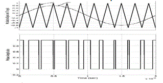 |
| Fig. 2 Sinusoidal Pulse Width Modulation Waveform |
| But at the same time, AC inverter can also causes harmonics in this drive and this harmonics will reduce the power factor and the motor performance gets affected in this system. The harmonic effects in induction motor are noise vibration, shaft deflection, overheating, excessive losses, harmonic torques, oscillation, low efficiency and shorten induction motor life operation. |
| Because of these problems, the harmonic filters have to be design by considering all of those factors. There can be different types of filters that are used in order to reduce the harmonic distortion. In which active harmonic filters are electronic devices that eliminate the undesirable harmonics on the network by inserting negative harmonics into the network. The Active Power Filters are normally available for low voltage networks |
ACTIVE POWER FILTER
|
| Active Power Filter offers flexible and versatile solution for mitigation of harmonic current and voltage to improve the voltage quality problems. They are connect to low and medium voltage distribution system in shunt or in series. Series Active Power Filter is connected to the system through a coupling transformer. The compensation voltage is used to cancel the voltage harmonics of the load. Source. The main aim of an shunt Active Power Filter (APF) is to generate compensating currents into inverter output for cancelling the current harmonics contained in the induction motor load current. This wi ll thus result in sinusoidal. The Active Power Filters consist of active components such as IGBT-transistors and gate pulse are generated by using Synchronous Reference Frame theory applied to space vector pulse width modulation. |
SYNCHRONOUS REFERENCE FRAME THEORY
|
| In this Synchronous Reference Frame theory based d-q model is discussed. Reference frame transformation refers to transformation from a-b-c to d-q-0 axes. Coordinates from a three-phase a-b-c stationery coordinate system to the d-q-0 rotating coordinate system is carried out. Here first transformation is from a-b-c to alpha-beta coordinates and second transformation is from alpha-beta to d-q-0 co-ordinates. Two different transformation matrix need to be required Clarke Transformation and park transformation. |
| A. Clarke Transformation |
| The forward Clarke (1943) transform does a magnitude invariant translation from a three phase system into two orthogonal components. If the neutral - ground connection is neglected, the sum of variables in a three-phase system (a-b-c) is equal to zero, and there is redundant information. Therefore, the system can be reduced to two variables, called αand βThe Clarke transform is given by: |
 |
| Reference frame theory based d-q model is presented. Instantaneous voltages in the a-b-c coordinates are transformed to two axis coordinates represented by α and β shown in Fig. 3. |
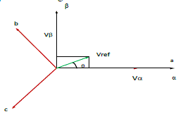 |
| Fig. 3 Vector Diagram for a-b-c to α-β axis |
| B. Park Transformation |
| The Park (1929) transform is a vector rotation, which rotates a vector (defined by its quadrature components) through a specified angle. The Park transformation is given by following set of equation: |
 |
| In three phases balanced system neutral current is zero, and zero sequence current does not exist. Voltage in α and β reference frame is express as shown in equation (2). The Voltage in α and β reference frame is further transform in rotating reference frame with ωr as angular velocity in d-q reference frame. . Instantaneous voltages in the α-β coordinates are transformed to d-q cordinates shown in Fig. 4. |
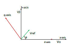 |
| Fig. 4 Vector Diagram for α-β axis to d-q axis |
| C. Proportional Integral Controller |
| The PI controller is very important part for the SAPF. It consists of proportional term and integral term. With this element, the best control performance of the SAPF is obtained. PI focuses on the difference (error) between the Process Variable (PV) and the Set-Point (SP), the difference between harmonics current reference signal IH and the filter current If . PI controller algorithm involves two separate parameters; the Proportional and the Integral. |
| The Proportional value determines the reaction to the current error; the Integral determines the reaction based on the sum of recent errors. Average sum of these two actions is used to adjust the process of the plant. By correctly "tuning" these two constants in the PI controller algorithm, the PI controller can provide control action designed for specific process requirements. |
| D. Closed Loop Current Control Scheme Using Synchronous Frame Theory |
| The control scheme shown in Fig. 5 consists of inner current control loop and outer voltage control loop. The PI controller of the voltage control loop gives a current command required to maintain the DC bus voltage to set value. This is added to the AC component of d axis of the load current. It gives the current reference value for d axis component . The reference for q axis is obtained after the orientation of load current. |
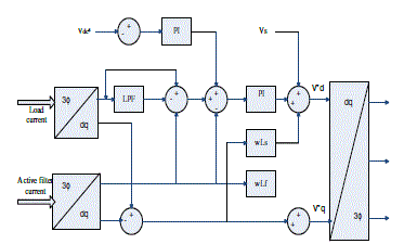 |
| Fig. 5 Block Diagram of Closed Loop Current Control Scheme Using SRF |
SVPWM
|
| SVPWM signals can be generated directly from the instantaneous reference phase voltages. Each reference phase voltage is compared with the triangular carrier, and the pole voltages for individual phase are generated independently of each other. To obtain the maximum possible peak amplitude of the fundamental phase voltage in linear modulation, a common mode voltage Voffset is added to the reference phase voltages, where the magnitude of Voffset is given by, |
 |
| Where Vmax the maximum magnitude of the three is sampled reference phase voltages and Vmin is the minimum magnitude of the three sampled reference phase voltages. |
SIMULATION RESULTS
|
| A. Variable Frequency Drive Without Active Power Filter |
| This section represents the simulation result of Variable Frequency Drive before connecting Active Power Filter by using MATLAB/SIMULINK. |
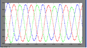 |
| Fig. 6 Output Current Waveform of VSI Fed Induction Motor. |
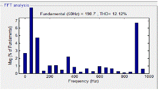 |
| Fig. 7 THD Level For VFD Without Filter. |
| Fig. 6 and Fig. 7 Shows output current waveform and FFT analysis of VFD without connecting active filter. This represents the presence of output current harmonics in load side. |
| B. Synchronous Reference Frame Transformation |
| The 3φ sine waves with 120 degree phase shift are converted to 2φ α-β and then converter to d-q axis .The transformation circuit is developed in the MATLAB/SIMULINK |
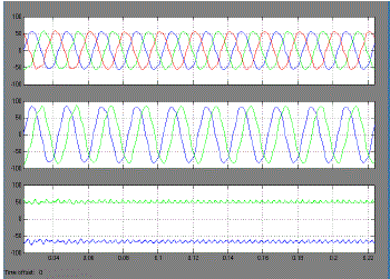 |
| Fig. 8 Output Waveform of Reference Frame Transformation. |
| Fig. 8 shows the Va,Vb,Vc sine wave with 120 degree phase shift is converted to 2φ wave form (αβ) that is 90 degree phase shift each other when α is 0 degree and β is 90 degree. Again α-β is transformed to d-q axis. |
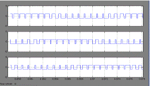 |
| Fig. 9 SVPWM Pulse generation for VSI. |
| Fig. 9 shows the gate pulse for VSI inverter. Three phase reference voltage is compared with the triangular carrier wave to produce gate pulse to VSI used in Shunt Active Power Filter. |
| D. Variable Frequency Drive With Active Power Filter |
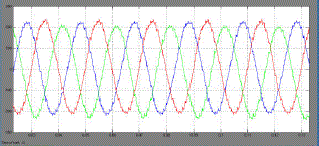 |
| Fig. 10 Output current waveform of VFD with filter. |
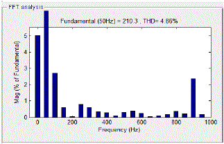 |
| Fig. 11 THD Level For VFD With Filter. |
| Fig. 10 and Fig. 11 Shows output current waveform and FFT analysis of VFD with connecting active filter. In this Shunt Active Power Filter (SAPF) is connected to load side in order to reduce the output current harmonics. The current control scheme proposed for Shunt Active Power Filter (SAPF) is Synchronous Reference Frame theory and SVPWM technique is employed to generate pulse to SAPF by using MATLAB/SIMULINK.. |
CONCLUSION
|
| In this paper Shunt Active Power Filter is developed for harmonic reduction in VSI based Induction motor drive. Here Synchronous Reference Frame theory with SVPWM technique is used for controlling the injection of the compensating current. From the simulation results it is observed that Total Harmonic Distortion (THD) is reduced from 12.12% to 4.86% using the proposed methodology in efficient manner. |
References
|
- JarupulaSomlal, VenuGopala, RaoMannam, “Analysis Of Discrete & Space Vector PWM Controlled Hybrid Active Power Filters For PowerQuality Enhancement,” International Journal of Advances in Engineering & Technology, Vol. 2, Issue 1, pp. 331-341, Jan 2012.
- M.Sunitha, B. N .Kartheek, “Elimination of Harmonics Using Active Power Filter Based on DQ Reference Frame Theory,” InternationalJournal of Engineering Trends And Technology, Vol. 4, Issue 4, pp. 781, April 2013.
- SangshinKwak, Hamid A. Toliyat, “A Hybrid Converter System for High-performance Large Induction Motor Drives,” IEEE Trans. Energy.Con., vol. 20, no. 3, pp. 504, Sep 2005.
- A. R. Beig and V. T. Ranganathan, “A Novel CSI fed Induction Motor Drive,” IEEE Trans. Power Electron., vol. 21, no. 4, pp. 1073-1082, Jul.2006.
- J. R. Espinoza and G. Joos, “A Current Source Inverter fed Induction Motor Drive System with Reduced Losses,” IEEE Trans. Ind. Appl., vol.34, no. 4, pp. 796-805, Jul./Aug. 1998.
- Chandani. M. Chovatia, Narayan P Gupta, Preeti N Gupta, “Harmonic Mitigation using Shunt Active at Utility end in grid connected toRenewable Source of Energy”International Journal of Emerging Technology and Advanced Engineering, Vol. 2, Issue 8, August 2012.
- M. H. Bierhoff and F. W. Fuchs, “DC Link Harmonics of Three Phase Voltage Source Converters Influenced by the Pulse Width ModulationStrategy-An Analysis,” IEEE Trans. Ind. Electron., vol. 55, no. 5, pp. 2085-2092, May 2008.
- G. Narayanan, D. Zhao, H. K. Krishnamurthy, R. Ayyanar, and V. T. Ranganathan, “Space Vector Based Hybrid PWM Techniques forReduced Current Ripple,” IEEE Trans. Ind. Electron., vol. 55, no. 4, pp. 1614-1627, Apr. 2008.
- SanguRavindra, V.C.Veera Reddy, S.Sivanagaraju, “Design of Shunt Active Power Filter to eliminate the harmonic currents and tocompensate the reactive power under distorted and or imbalanced source voltages in steady state,” International Journal of Engineering TrendsAnd Technology, Vol. 2, Issue 3, pp. 20, April 2011.
- G.K Nisha, IAENG, S.Ushakumari and Z.V Lakaparampil, “Harmonic Elimination of Space Vector Modulated Three Phase Inverter,”Proceedings of the International Multi conference of Engineer and Computer Scientists, vol. 2, IMECS 2012, March 14-16, 2012.
|