Keywords
|
| Synchronous Reference Frame (SRF),power line conditioners (PLCs), APF. |
INTRODUCTION
|
| RECENTLY, power quality and custom power have beenhot topics because of the widespread use of nonlinear electronic equipmentsuch as diode/thyristor rectifiers, switched mode power supply (SMPS), welding equipment, incandescent lighting, and motor drives are degrading power quality in transmission and distribution grid systems. These non-linear loads result in harmonic or distortion current and create reactive power problems. Harmonic suppression and reactive power compensation are essential for the construction of smart grid, which gathers, distributes, and acts on the behaviour of suppliers and consumers in order to improve the efficiency and sustainability of electric services. With the increasingly widespread application of power electronic device, such as electronic appliances, switching model power supplies and electronic ballasts, the harmonic contamination they produce in grid has given rise to a variety of safety concerns. In a comparative study, the traditionally proposed LC passive filter could only absorb harmonic waves of a specific frequency, whereas the active power filter (APF) is capable of handling harmonics ranging between fluctuating frequencies and simultaneously maintaining a good compensative performance These harmonics induce malfunctions in sensitive equipment, overvoltage by resonance, increased heating in the conductors and harmonic voltage drop across the network impedance that affects power factor. Traditionally passive filters have been used to compensate harmonics and reactive power; but passive filters are large in size; aging and tuning problems exist and can resonate with the supply impedance. Recently active power line conditioners (APLC) or active power filters (APF) are designed for compensating the current-harmonics and reactive power simultaneously. |
ACTIVE POWER FILTER SYSTEM
|
| Basic Compensation Principle |
| The compensation objectives of active power filters are the harmonics present in the input currents iLu, iLv, and iLw of the load. Since the compensating currents iCut iCv, and iCw are controlled so as to eliminate the harmonic currents of the load, the source currents is becomes sinusoidal. |
| Power Circuit Configuration |
| Fig. 1 shows the active power filter system developed in this paper. The quadruple voltage source PWM converters are adopted as the power circuit. Note that the primary windings of the four three-phase transformers are connected to each other in series. So, the primary voltage of each transformer is 50V and the secondary is 100V. The primary windings of the four transformers can be connected to each other in parallel if the transformers of primary voltage (200V) and secondary voltage (100V) are applied. The multiple converters in parallel, however, are less efficient than those in series because of the increase of harmonic currents in each secondary winding and converter. The converter is a conventional three-phase bridge converter consisting of six power transistors and six power diodes connected back-to-back, as shown in Fig. 2. The turn-off time of the power transistors was about 15, us and nearly equal to that of large capacity GTO thyristors. |
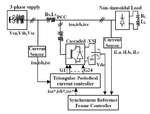 |
| Figure.1 schematic diagram of proposed converter |
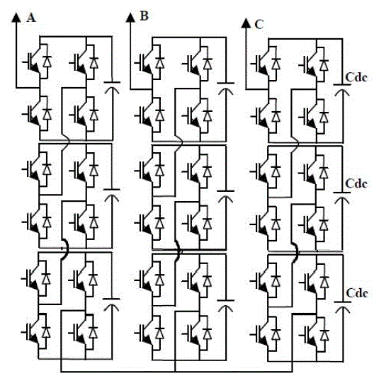 |
| Figure.2 schematic diagram of five level three phase inverter |
PROPOSED CONTROL STRATEGIES
|
| The proposed control system consists of reference current control strategy using SRF method and triangularperiodical current modulator for switching signals of cascaded VSI. |
| A. SRF Control strategy: |
| The synchronous reference frame theory is developed in time-domain based reference current generation techniques. The SRF is performing the operation in steady-state or transient state as well as for generic voltage and current; it’s capable of controlling the active power filters in real-time system. Another important characteristic of this theory is the simplicity of the calculations, which involves only algebraic calculation. The block diagram of the synchronous reference frame controller is shown in Fig 3. |
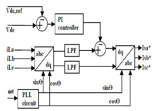 |
| Figure.3 synchronous reference frame theory |
| The basic structure of SRF methods consists of direct (d-q) and inverse (d-q)-1 park transformations, which allow the evaluation of a specific harmonic component of the input signals. The reference frame transformation is formulated from a three-phase abc stationery system to the two-phase direct axis (d) – quadratic axis (q) rotating coordinate system. In a-b-c stationary axes are fixed on the same plane and separated from each other by 120º. These three phase space vectors stationary coordinates are easily transformed into two axis d-q rotating reference frame. This proposed algorithm derivate from a threephase stationary coordinate load current iLa, iLb, iLc are convert to id-iq rotating coordinate current, as follows |
 |
| The d-q transformation output signals depend on the load currents (fundamental and harmonic frequency components) and the performance of the phase locked loop. The PLL circuit of rotation speed (rad/sec) of the rotating reference frame ωt set as fundamental frequency component. The PLL circuit is providing sinθ and cosθ for synchronization. The id-iq current passed through low pass filter (LPF) for filtered the harmonic components and allows only the fundamental frequency components. The LPF design is based on Butterworth method and the filter order is 2. The band edge frequency is selected the fundamental of 50 Hz for eliminate the higher order harmonic components. Proportional Integral (PI) controller is used to eliminate the steady state error of the DC-component of the cascaded multilevel inverter and maintains the dc-side capacitor voltage constant. The dc capacitor voltage is sensed and compared with reference voltage for calculate the error voltage. These error voltages involved the P-I gain (KP=0.1 and KI=1) for regulate the capacitance voltage in the dynamic conditions. In accordance to the PI controller output is subtracted from the direct axis (d-axis) of harmonic component for eliminate the steady state error. The algorithm is further developed to the desired reference current signals in dq rotating frame is converted back into abc stationery frame. The inverse transformation from dq rotating frame to abc stationery frame is achieved by the following equations |
 |
| The reference frame is rotates synchronous with fundamental currents. Therefore, time variant currents with fundamental frequencies would be constant after transformation. Thus, currents would be separated to DC and AC components. AC components of d-axis and in q-axis current are used for harmonics elimination and reactive power compensation. |
| In recent years, multilevel converters have shown some significant advantages over traditional two-level converters, especially for high power and high voltage applications. In addition to their superior output voltage quality, they can also reduce voltage stress across switching devices. Since the output voltages have multiple levels, lower dv/dt is achieved, which greatly alleviates electromagnetic interference problems due to high frequency switching. Over the years most research work has focused on converters with three to five voltage levels, although topologies with very high number of voltage levels were also proposed. In general, the more voltage levels a converter has the less harmonic and better power quality it provides. However, the increase in converter complexity and number of switching devices is a major concern for multilevel converter. There are several topologies available, being the Neutral Point Clamped, Flying Capacitor and Cascaded H-bridge inverter the most studied and used. In recent years many variations and combinations of these topologies have been reported, one of them is the cascaded H-bridge. |
MULTILEVEL INVERTERS
|
| Multilevel converters have been introduced as static high-power converters for medium- to high-voltage applications such as large electric drives, dynamic voltage restorers, reactive power compensations, and FACTS devices. The multilevel converters synthesize a desired stepped output voltage waveform by the proper arrangement of the power semiconductor devices from several lower dc voltage sources. The main advantage of multilevel converters is the use of mature medium power semiconductor devices, which operate at reduced voltages. As a result, the switching losses and voltage stress on power electronic devices are reduced. Also, the output voltage has small voltage steps, which results in good power quality, low-harmonic components, and better electromagnetic compatibility. Multilevel converters have obtained more and more attention in recent years and new topologies with a wide variety of control strategies have been developed. There are three different basic multilevel converter topologies: neutral point clamped (NPC) or diode clamped, flying capacitor (FC) or capacitor clamped, and cascaded H-bridge (CHB). |
| The main drawback of the NPC topology is unequal voltage sharing between the series connected capacitors, which leads to dc-link capacitor unbalancing and requires a great number of clamping diodes for a high number of voltage levels. Also, the maximum voltage across the switches is closest to the switching node. Therefore, the three-level NPC converter has been commercialized in industry as a standard topology. The FC multilevel converter, and the stacked multilevel (SM) converter, uses flying capacitors as clamping devices. These topologies have several attractive properties compared to NPC converters, including the advantage of transformer-less operation and have redundant phase leg states that allow the switching stresses to be equally distributed among semiconductor switches. But, these converters require an excessive number of storage capacitors for a high number of voltage steps. |
| A double FC multi-cell converter has been presented. This topology has been implemented by adding two low frequency switches to the conventional configuration of the FC multilevel converter. The main advantages of the presented converter, in comparison with the FCmultilevel and SM converters, are the doubling of the rms value of the output voltage and the number of output voltage steps and the cancelling of the midpoint of the dc source. But two additional switches must operate at the peak of the output voltage. This restricts high-voltage applications of this converter. The CHB topologies are a good solution for high-voltage applications due to the modularity and the simplicity of control. But, in these topologies, a large number of separated voltage sources are required to supply each conversion cell. To reduce the number of separate dc voltage sources for high-voltage applications, new configurations have also been presented; however, a capacitor-voltage balancing algorithm is required. |
SIMULATION RESULTS
|
| Simulations are implemented using MATLAB/SIMULINKsoftware and the results confirm effectiveness of the proposed method in balancing power sharing among different inverter cells and requiring smaller DC voltage sources. This session is divided into two cases in which Case1 nonlinear loads connected to grid and its effect on source side and Case2.1active power filter connected to the grid along with nonlinear load. The APF is used to serve the load harmonics and maintain reduced source current harmonics. |
| Case 1: Modeling of nonlinear loads connected to grid |
| Figure 4 shows the Matlab/Simulink Model of nonlinear loads connected to grid. Universal bridge is considered as nonlinear load. In universal bridge diodes are considered since every power electronic device is the cause of harmonics. Diode is considered because no control circuit is required. |
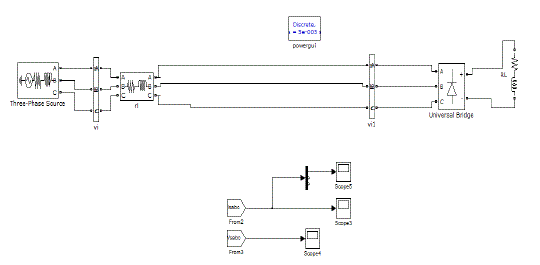 |
| Figure4Matlab/Simulink Model of nonlinear loads connected to grid |
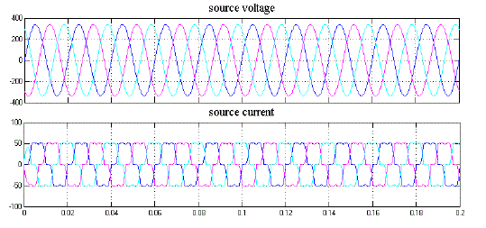 |
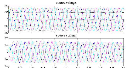
| Figure. 5Matlab/Simulink results of nonlinear loads connected to grid |
| Fig.5 shows the sinusoidal source voltage and non- sinusoidal source currents.Three phase voltages are considered here and source current of three phases are influenced by non-linear load. Fig.6 shows the source power factor considered in single phase voltage and single phase current. Fig.7 shows the harmonic spectrum and THD value is observed to be 19.45% of fundamental. |
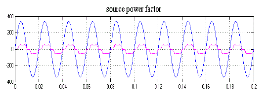 |
| Figure 6: Matlab/Simulink result of source power factor |
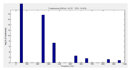 |
| Figure 7: Matlab/Simulink Model of harmonic spectrum |
| Case 2.1: Modeling of active power filter along with non linear load connected to grid |
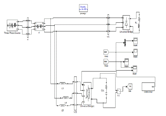 |
| Figure 8: Matlab/Simulink Model of nonlinear loads connected to grid along with APF |
 |
| Figure 9: Matlab/Simulink result of grid connected APF along with non- linear load |
| Fig. 8 shows the MATLAB/Simulink model of APF connected to grid along with non-linear load. In this case only normal inverter is used to compensate source current.Fig.9 shows harmonic compensated source current using APF. It utilizes normal inverter, so the harmonic content is not eliminated completely. This can be depicted using harmonic spectrum which is shown in fig.10. Fig.10 shows the harmonic spectrum and THD, it is observed that THD is reduced to 11.75% of fundamental. |
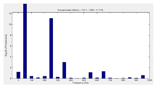 |
| Figure. 10Matlab/Simulink Model of harmonic spectrum of grid connected APF with normal inverter |
| Case 2.2: Modeling of active power filter using multilevel inverter along with non linear load connected to grid |
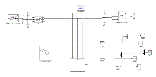 |
| Figure 11:Matlab/Simulink Model of nonlinear loads connected to grid along with APF using multilevel inverter |
| Fig.11 shows the MATLAB/Simulink model of a multilevel inverter based APF. The multilevel inverter is designed for three phase since it is connected to a three phase grid for compensating three phase harmonic current. Figure 13 shows the Matlab/Simulink model of harmonic spectrum of APF which employed multilevel inverter. The harmonic spectrum indicates that THD value is reduced to 2.06% of fundamental. Above Figure 14 shows the improved source power factor of a three phase grid connected APF along with nonlinear load. This APF employs a multilevel inverter, which is more effective than a normal inverter. |
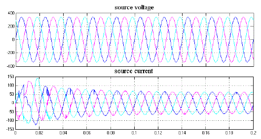 |
| Figure 12: MATLAB/SIMULINK result of compensated source current |
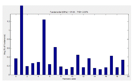 |
| Figure 13:Matlab/Simulink Model of harmonic spectrum of grid connected APF with multilevel inverter |
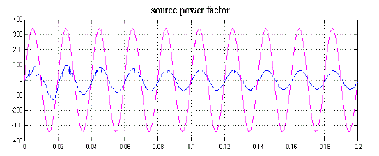 |
| Figure14: MATLAB/Simulink result of source side power factor of one phase current and voltage |
CONCLUSION
|
| This paper presents anAPF which utilizes multilevel inverter to compensate source current harmonics. A SIMULINK based model is developed and Simulation results are presented. The DC voltage used for inverter is obtained from non-renewable energy source. Thus obtained DC is fed to cascaded H-bridge to obtain multilevel output. The number of levels obtained is seven. Thus obtained output AC of inverter contains harmonic content this harmonics are compared in SRF theory to produce a signal which is used as reference to compensate source harmonics. Thus obtained AC is interconnected with grid. A comparison is illustrated between APF employing normal inverter and APF employing multilevel inverter. It is shown that APF employing multilevel inverter is more effective than APF employing normal inverter. All the simulation is analyzed in MATLAB/SIMULINK R2009b version. |
References
|
- Karuppanan P and KamalakantaMahapatra” A Novel SRF Based Cascaded Multilevel Active Filter for Power Line Conditioners” Annual IEEE IndiaConference (INDICON) 2010 978-1-4244-9074-5/10
- Huang SJ, Wu JC. Design and operation of cascaded active power filters for the reduction of harmonic distortions in a power System. IEEE Proc.-GenerTrans Distrib 1999; 146(2): 193-199..
- Peng FZ, McKeever JW, Adams DJ.Power Line Conditioner Using Cascade Multilevel Inverters for Distribution Systems.IEEE Trans on Indu. Appl.1998; 34(6): 1293-98.
- Hpenbrock U.The FBD method a generally applicable tool for analyzing power relations. IEEE Trans on Power Sys 1993; 8(2): 381-387.
- Akagi H,Nabae A, Atoh S. Control Strategy of Active Power Filters Using Multiple Voltage-Source PWM Converters. IEEE Trans on Industry Applications 1986;IA-22(3): 460-465.
- Watanabe EH, Stephan RM, Aredes M.New Concepts of Instantaneous Active and Reactive Powers in Electrical Systems with Generic Loads.IEEETrans. Power Delivery 1993.
- Peng FZ, Lai J-S. Generalized Instantaneous Reactive Power Theory for Three-Phase Power Systems.IEEE Trans. on Instrument and Measurement1996.
- Bhattacharya S, Divan D. Synchronous frame based controller implementation for a hybrid series active filter system. IEEE-conference paper 1995;2531-40.
- Singh B, Al-Haddad K, Chandra A. A New Control Approach to 3- phase Active Filter for Harmonics and Reactive Power Compensation. IEEE Trans.on Power Systems 1999; 46(5): 133-138.
- Pigazo A, Moreno VM, Estebanez EJ.A Recursive Park Transformation to Improve the Performance of Synchronous Reference Frame Controllers inShunt Active Power Filters.IEEE Trans on Power Electronics 2009; 24(9).
- Bhattacharya S, Frank TM, Divan DM, Banerjee B. Parallel active filter system implementation and design issues for utility interface of adjustablespeed drive systems. IEEE Conference 1996; 1032-1039.
- Malinowkski M, Gopakumar K, Rodriguez J, Perez MA. A Survey on Cascaded Multilevel Inverters.IEEE Trans on Industrial Electronics 2010; 57(7).
- Karuppanan P, Mahapatra KK. Shunt Active Power Line Conditioners for Compensating Harmonics and Reactive Power. Proceedings of theInternational Conference on Environment and Electrical Engineering (EEEIC), 2010; 277-280.
- Akagi H, Nabae A, Atoh S. Control Strategy of Active Power Filters Using Multiple Voltage-Source PWM Converters. IEEE Trans on IndustryApplications 1986; IA-22(3): 460-465.
|