ISSN ONLINE(2319-8753)PRINT(2347-6710)
ISSN ONLINE(2319-8753)PRINT(2347-6710)
Muralikrishna Allem1, J.O.Chandle2
|
| Related article at Pubmed, Scholar Google |
Visit for more related articles at International Journal of Innovative Research in Science, Engineering and Technology
This paper presents a method of finding weakest area and line in complex power system network which comprises of a 57 bus and 6 generator system (IEEE 57-bus system). The case studies have been analyzed by considering the effect of generator outages and other abnormal loadings. This method uses a voltage stability index parameter to decide the maximum loading of the line beyond which line gets voltage collapse causing the surrounding area to get diverged from its normal stable point... The parameter called basic line stability index is derived and used to analyze whether the weakest area and the line in the complex network is far away from voltage collapse point or not. This index gives the idea about the voltage divergence point of the line and area of the system. The simulation results have been obtained by MATLAB programming for a 57 bus system. The main aim of using this method is to help the operators at load control centers to avoid blackouts which are serious problems of modern power system network.
Keywords |
| Basic line stability index, Divergence,Blackouts, Maximum loadability,Generator outages |
ABBREVATION |
| Blsi=basic line stability index. |
INTRODUCTION |
| The methods to avoid problems of voltage collapse has been being observed in many areas in the world and has been being investigated for past one decade[2-4].The major disturbance in power system network is voltage stability related blackouts. This abnormal disturbance is due to overloading and line outages. Maintaining Voltage stability has become a challenging and focusing area for power utilities under abnormal changes in power system [1], [5-8]. This method gives an idea in such a way that load operator can anticipate the problem thus avoids the blackouts and related problems. This paper anticipates a stability index that is Blsi (basic line stability index) for all lines in the given IEEE 57 bus system under some disturbances and gives indication and alarm signal to load control centre that particular line and area get diverged. |
RELATED WORK |
| Voltage instability was the most significant problem as it destructs the entire power network making the network to be isolated from other stable network. This problem was analysed by so many researchers to give their contribution in avoiding the problems pertaining to voltage instability. Some of the methods and techniques that were contributed by researchers had been used only in off-line based applications. But off-line applications would not give real time status so as to trace the system health. Change in climatic conditions affects the power flow in the line. We can predict this by employing the methods which are best suited for on-line applications. So many methods that had been adopted in finding the solution towards voltage instability problems were discussed in [9-13].The method that is introduced in this paper also best suited for on-line application making it as a efficient method to trace electrical quantities in the system in real time manner |
PROPOSED METHODOLOGY |
| The concept of basic line stability index is understood by the following theory and derivation. For example if we consider the transmission line (m-n) in the network which is to be monitored , the parameters to be considered for deriving the basic line stability index for the line(m-n) is given below. |
| 1).a voltage magnitude Vm at a sending bus m, of each transmission line (m-n), |
| 2). a voltage magnitude Vn at a receiving bus n of each transmission line (m-n), |
| 3). a sending bus voltage angle δm , |
| 4). a receiving bus voltage angle δn , |
| 5). a line power flow Pmn+ jQmn charging reactive power added at the receiving bus, |
| 6). a line power flow Pm+jQm with a charging reactive power added at sending bus, |
| 7). Pm+jQm * the line power flow after the charging reactive power at the sending bus m, |
| 8). Pmn+jQmn * the line power flow before the charging reactive power at the receiving bus n, |
| 9). Rmn+Xmn is the line impedance |
| 10). Y indicates half of the grounding admittance of the line (m-n). |
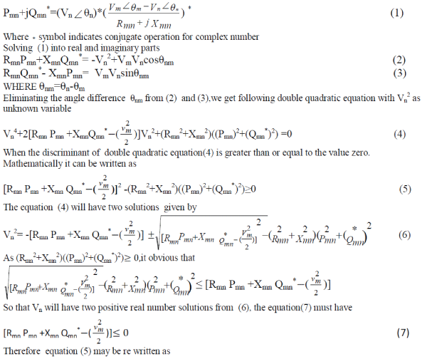
| The line power flow equation of Pmn+jQmn * can be expressed as |
 |
 |
| (where Blsi represents basic line stability index). |
| From the derived index in Equation (8), the following observations are found: |
| 1. The Blsi should be larger than or equal to the value 1.0(one), that indicates the receiving bus voltage Vn will have a mathematical solution(real value) that is operational in real life. |
| 2. The Blsi can be used to anticipate the status of the weak lines (branches) and weakest areas in a system. |
| 3. Whichever the line is approaching to the value 1 or less than it ,that particular line is considered to be diverged from its normal operating state. |
SIMULATION AND RESULTS |
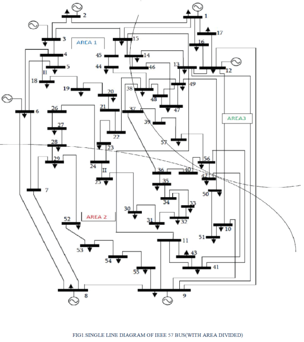
| This method is applied for practical IEEE 57 test bus system.This IEEE 57 bus system is well known as six machines (generators) and 57 bus system. Various conditions like increment in loading levels at PQ buses, increment in generations at PV buses and various generator outages were considered to check the basic line stability index(Blsi) which gives the idea about system divergence point from its Stable operating point. |
| Single line diagram of IEEE 57 bus and 6 generator test system with areas divided is shown in FIG 1. |
| A.CASE |
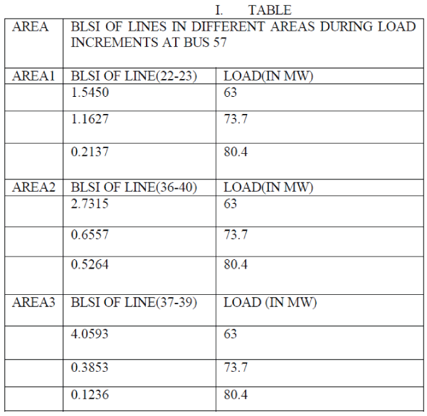
| DURING LOAD INCREMENT AT BUS 57,BLSI OF LINES IN 3 DIFFERENT AREAS OBSERVED AS FOLLOWS |
 |
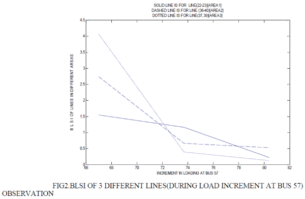 |
| Before 72 MW loading,the line (22-23) in area 1 is more likely to get collapse than the lines in other areas. |
| After 72 MW loading level ,the line(36-40)in area2 is more likely to get collapse than the lines in other areas. |
| B.CASE |
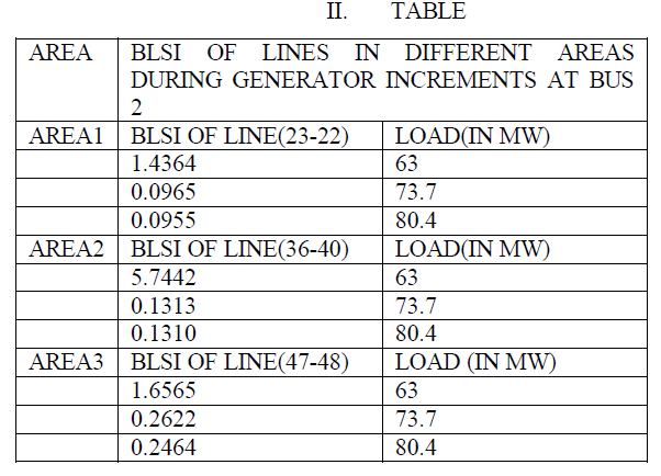
| DURING GENERATOR INCREMENT AT BUS 2,BLSI OF LINES IN 3 DIFFERENT AREAS |
 |
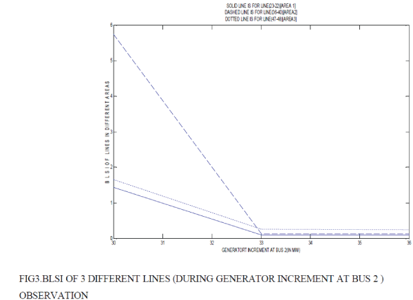 |
| BEFORE AND AFTER 33MW,THE LINE(23-22) WHICH IS IN THE AREA 1 IS MORE LIKELY TO GET COLLAPSE THAN THE OTHERS .IT IS OBSERVED THAT IN ALL CONDITIONS,AREA1 IS WEAKEST AREA. |
| C.CASE |
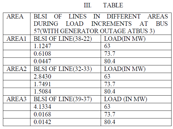
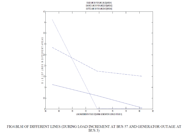
| DURING LOAD INCREMENT AT BUS 57,BLSI OF LINES IN 3 DIFFERENT AREAS OBSERVED AS FOLLOWS(WITH GENERATOR OUTAGE AT BUS 3 IS CONSIDERED) |
 |
 |
| OBSERVATION |
| BEFORE 73 MW,AREA1 IS WEAKEST AREA |
| AFTER 73 MW,AREA3 IS THE WEAKEST AREA. |
 |
CONCLUSION |
| Thus We have implemented a method called stability index method in a system comprises of 57 buses and 6 generators to observe the voltage divergence point of each power line in the system. This method will be helpful to power utilities and operators at load control centres to monitor the complex system with corrective actions at specific locations where the line get easily diverged from normal state. This method also predicts the weakest region and the weakest line in IEEE 57 bus system. |
ACKNOWLEDGEMENT |
| It is our primary duty to sincerely thank our life long encouragers (parents) DR.Poshetty and Saroja. They have loved and supported me longer than anyone, regardless of my faults. . For this I am truly grateful. I wish to acknowledge and thank my guide J.O.chandle, Professor, electrical engineering department , vjti, Mumbai. Her valuable guidance throughout my studies has been an invaluable contribution to my academic and professional development.. I also acknowledge Mr. vamshi Krishna (brother), for his support throughout the project. |
References |
|