ISSN ONLINE(2319-8753)PRINT(2347-6710)
ISSN ONLINE(2319-8753)PRINT(2347-6710)
Mr. Rajkumar D. Patil1, Prof. P. N. Gore2
|
| Related article at Pubmed, Scholar Google |
Visit for more related articles at International Journal of Innovative Research in Science, Engineering and Technology
The present study was carried out to assess the water quality of River Hemavathi during pre-monsoon season. It is one of the major tributary of river Kaveri. The water samples were collected near a village Turuvekere at two different points. Sample S1 was collected from the populated area of the village and Sample S2 one km upstream. The various physico-chemical parameters studied were temperature, pH, conductivity, TDS, turbidity, hardness, alkalinity, concentration of Ca2+, Mg2+ and Cl─ ions etc. All these parameters were then compared with the WHO and ISI standards to draw the final conclusion on the quality of water of the river.
Keywords |
| torsion test, ASTM, Nadai method, specimen geometry, torque, twist angle, stress–strain curve, FEA |
INTRODUCTION |
| Mechanical testing plays an important role in finding fundamental properties of engineering materials. These can be used in development of new materials. For a material to be used in engineering structure subjected to a load, it is important to know the strength and rigidity of the material to withstand the loads. As a result, numbers of experimental techniques have developed by engineers for mechanical testing of engineering materials. These materials may be subjected to tension, compression, bending or torsion loading. To test the material in torsion the proper test procedure is needed. It involves mounting a specimen on the testing machine. The torque is applied incrementally and both the applied torque and the corresponding angle of twist are measured. Using the appropriate formulae, relationships and the measured dimensions, shear stress and shear strain can be determined. Then, plot the torque vs. angle of twist, and shear stress vs. shear strain curve. From which material shear properties can be determined. [1] |
| Adequate construction of the failure criterion involves an experimental study of fracture in different types of stress state, while the experiments in tension and compression traditionally used for this purpose are not enough. For the construction of the fracture surface in this case, besides compression and tension experiments, additional shear tests as well as combined biaxial tests with thin-walled tubular specimens of different geometry should be conducted.[2] Zarroug et al. [3] examines the results obtained from combined tension–torsion loading tests carried out on Mild steel (En8) specimen. The results from the finite element analysis (FEA) are validated against experimental results. |
| Graber et al. [4] applied new approximate method for calculating stress-stain curves from torsion test results. For obtaining best accuracy the use of thin walled tubular specimens is recommended especially when the flow curve deviates strongly from the exponential Ludwig-Holloman law. The calculation also makes use of the concept of the “effective” length during deformation for short specimens. |
| Pavel et al. [5] conducted experiments for the failure criterion construction in a torsion test on solid or thick-walled cylindrical specimens. |
| Berto et al. [6] conducted 70 new fracture tests on notched specimens made of polymethyl-methacrylate. All torsion tests are carried out at room temperature under torsion loading conditions. Semi-circular notches as well as U- and Vnotches (with an opening angle equal to 120°) are used, with a root radius ranging from 0.1 to 7.0 mm. Plots of torque loads versus twist angles are recorded varying the notch root radius and the notch depth. |
| Han-Chin Wu et al. [7] conducted series of experiments on cast and extruded high purity aluminium material under monotonic large strain torsion condition. Both free-end and fixed-end torsions studied using tubular specimens of different gage lengths (long, medium and short). The torque versus angle of twist curves were recorded and converted into true shear stress–strain curves by use of the modified Nadai method. The axial extension for free-end torsion and the axial stress developed during fixed-end torsion are recorded. The effect of specimen geometry is studied. It is found that the long, thick-walled tubular specimen suitable for torsion test in the large strain range. |
| Bressan et al. [8] worked for developing, testing and operating a computerized prototype machine. The equipment consists of a horizontal torsion machine composed of an electric motor, a wheel, a horizontal shaft and a control and acquisition data system. An encoder obtains the torsion angle and the torque is measured by a load cell. Experimental tests are carried out at a constant angular speed that imposed a constant shear strain rate to the test specimen. The torsion tests have been performed on annealed materials such as 1020 steel, brass, pure copper and pure aluminium. The strain rate sensitivity parameter m has been evaluated from the equivalent stress versus strain curve from tensile and torsion tests. In torsion tests the m-values were 0.072 and 0.045 for steel and brass. |
| Utpal Borah et al. [9] developed multiaxial state of deformation kinematics and stresses in bulk metal forming processes, evaluation of workability calls for materials testing using combined axial and torsion tests. A high temperature combined axial and torsion testing system (ATTS) is developed for assessing workability of various materials under multi-axial state of stress and deformation conditions up to 1300 °C. In this paper, results from finite element modelling of axial torsion tests and seamless tube extrusion are presented. |
II. EXPERIMENTATION |
| The problems associated with torsion tests are : the homogeneity of the material, the strain measurement, the specimen geometry, and the determination of the shear stress-strain curve from the experimental torque versus angle of twist curve. These problems are explained as follows: |
| 1. The material homogeneity: If the material is not homogeneous, non-uniform deformation will occur, leading to regions that remain almost undeformed while plastic deformation occurring in the remaining part of the specimen. The strain concentration will lead to an early development of shear band localization in the specimen. This is a very serious problem, especially when long gage-length specimens are used. |
| 2. The strain measurement: An important problem associated with the torsion test and the combined axial-torsion test is the strain measurement. The method does not lead to accurate strain measurements due to the geometry of the specimen which has enlarged ends. |
| 3. The specimen geometry: Torsion tests have been conducted by use of tubular specimen, solid shaft. Tubular specimens are used in most of research. The advantages for this type of specimen are: (a) accurate shear strain measurement may be obtained because of the long gage section that this type of specimen has; (b) accurate strain measurements may be obtained in axial and hoop strains; (c) the specimen may be used for combined axial-torsional testing; (d) the specimen is suitable for test involving unloading/reloading/cyclic loading; and (e) the specimen may be used for investigation of shear band localization. The axial strain mentioned in (b) is greatly influenced by the specimen geometry Solid shafts can achieve very large strain without buckling. |
| 4. The determination of shear stress-strain curve: It uses a theory to convert the torque versus angle of twist curve into the shear stress-strain curve. Most of the theories such as Nadai [1950] or Canova et al. [1982] do not account for length change of the specimen subjected to torsion and, therefore, do not lead to accurate results for free-end torsion. Although the method can be used to obtain accurate shear stress-strain curve for the fixed-end torsion test [Wu et al., 1997]. Therefore, the free-end torsion of tubular specimens is still a practical test for the determination of true shear stress-strain curve. For this purpose, experimental data for axial and hoop strains are also needed. Based on the Nadai method, Wu et al. [1992, 1997] developed a method which, by accounting for the axial and hoop strains, provides a true shear stress-strain curve from the free-end torsion test. This true shear stress-strain curve is consistent with that determined from the fixed-end torsion test. |
| The loading of the specimen is carried out in different modes: (i) maintaining tensile force or axial displacement constant and increasing torque or angle of twist (ii) maintaining torque or angle of twist constant and increasing load or axial displacement.[3] Experimentation is carried out for different specimen geometry of different materials like mild steel, aluminium. The torque and angle of twist is recorded by varying load. The stress-strain curve plotted from recorded data by using Nadai method and value of modulus of rigidity is determined. Also the strain rate parameter is determined at room temperature. To study the effect of specimen geometry on torsion test results. The dimensions of |
| specimens such as gauge length, fillet radius and diameters are varied and the effect on deformation curves is studied. A new effective radius is proposed for calculation of strains and shear stresses from toque-twist data for solid specimens. |
III. EXPERIMENTAL RESULTS |
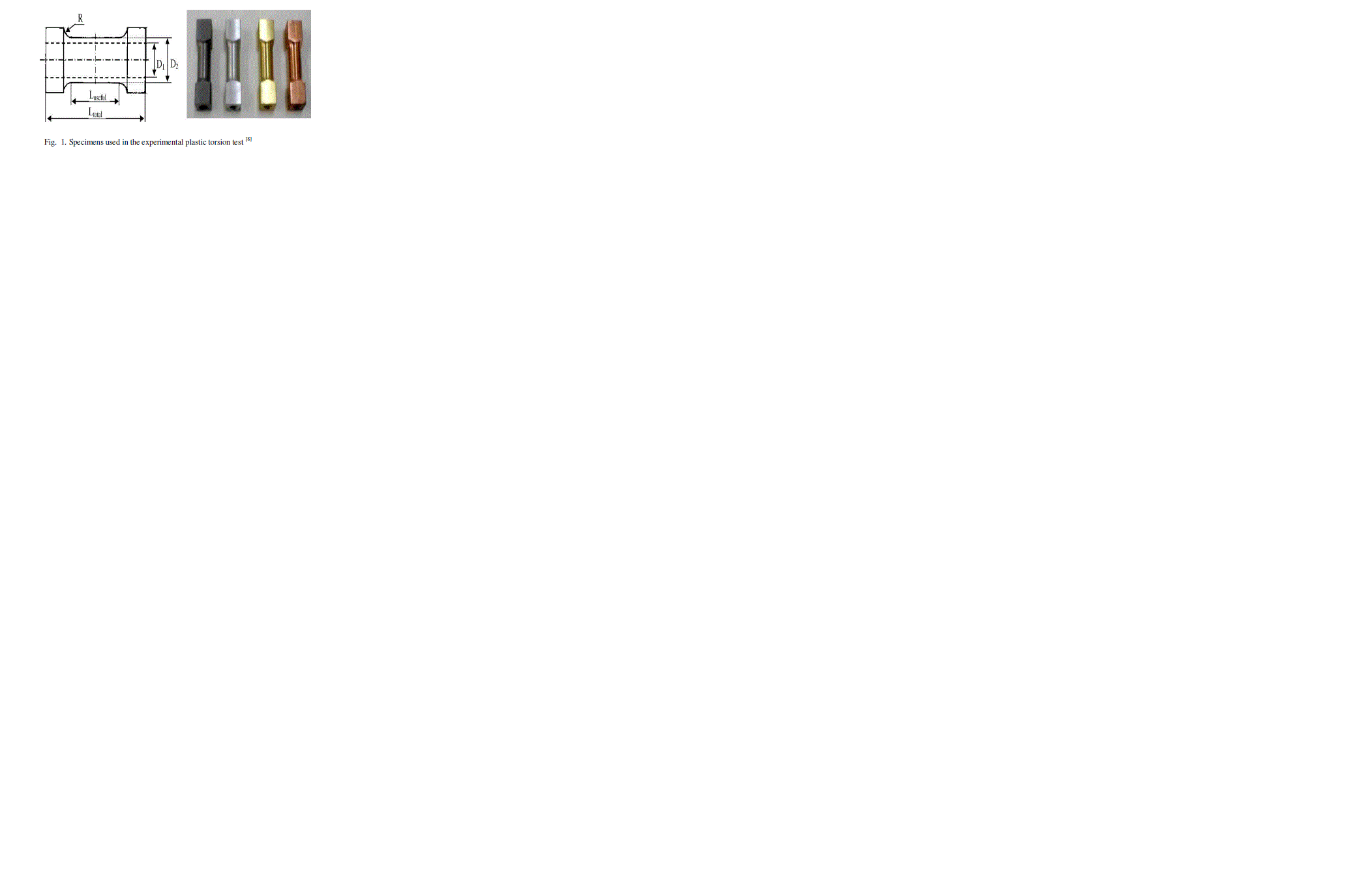 |
| In Fig. 1, the torsion test specimens for materials like aluminium, steel, brass and copper are shown. The specimens are hollow and specimens are designed according to stiffness criteria. |
| In table 1, different dimensions for hollow specimens are shown. |
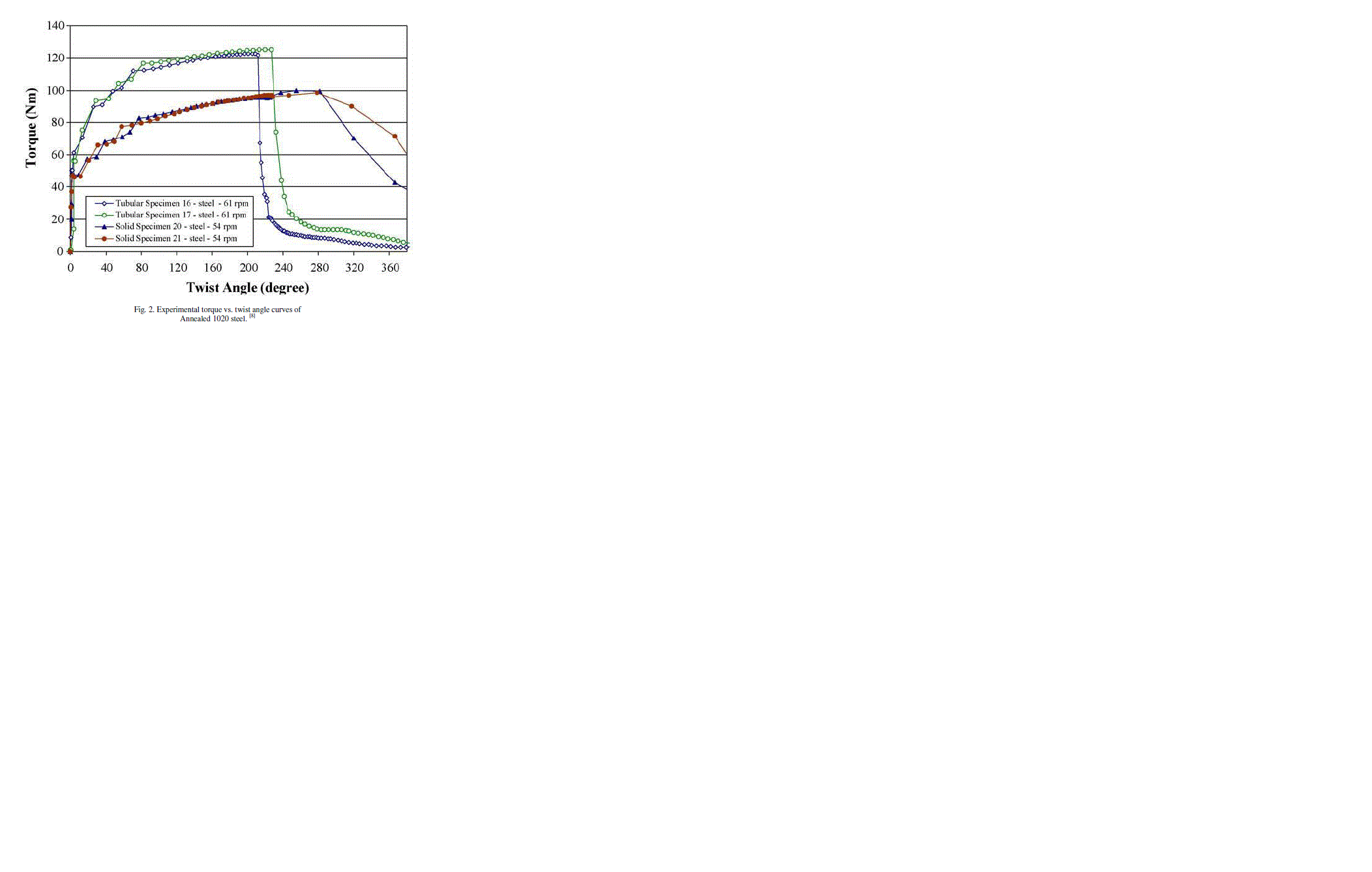
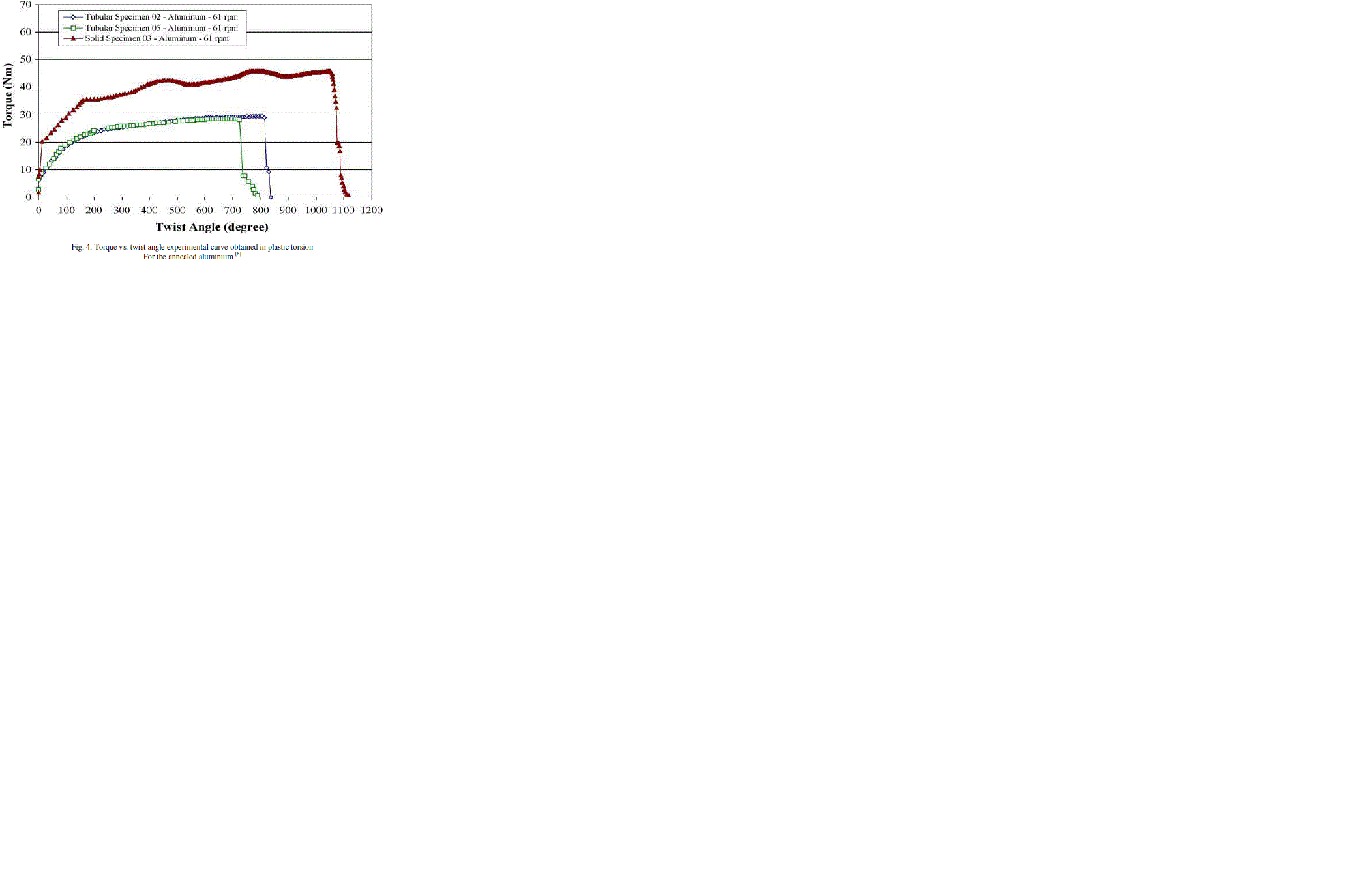
| In Figs.2 and 4, the torsion curve results of the present torque versus the twist angle for the plastic torsion tests for commercial pure aluminium and 1020 steel are shown. |
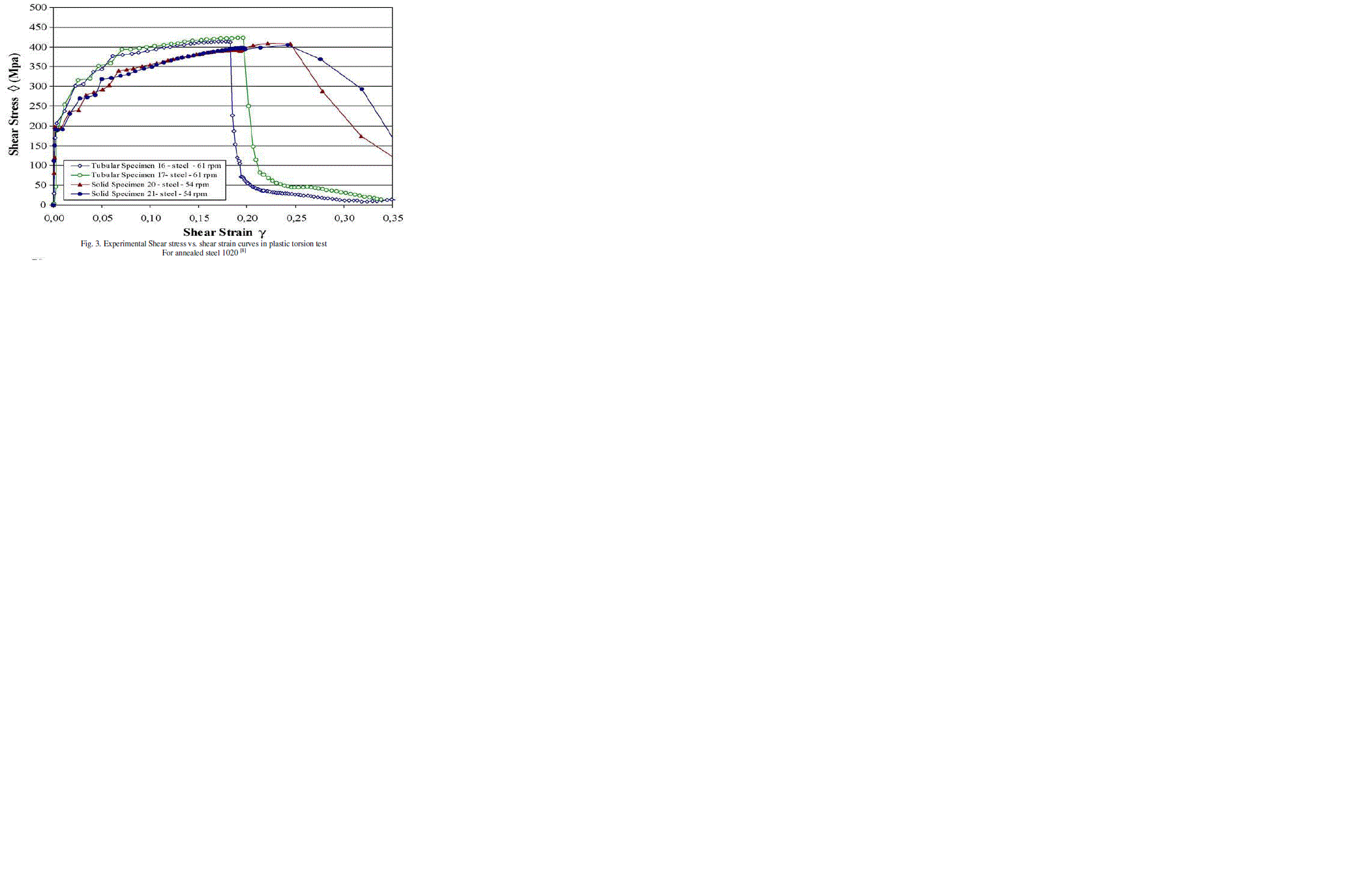
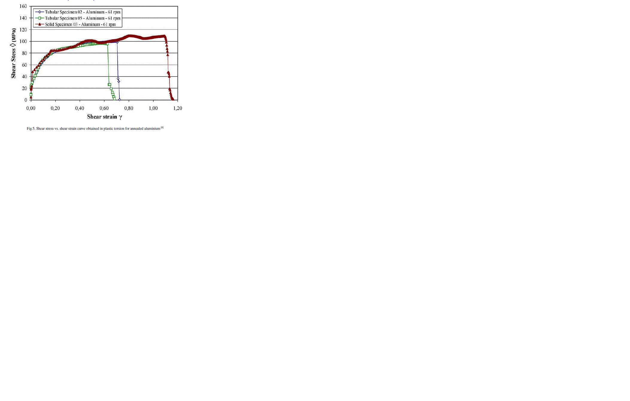
| The graphs in Figs. 3 and 5 represent the shear stress versus shear strain curves for these materials. |
| In Fig. 3, the difference between the solid and tubular specimens plastic behaviour can be observed. The solid specimen yields a lower curve and a larger elongation or a shear strain to rupture. Thus, the hardening curves are different, the solid specimen showing a lower work-hardening coefficient. In the tubular specimen, the shear stress gradient across its thickness is negligible but in the solid specimens are not. The shear stress rupture point shown in the plotted curve is very clear. Thus, the tubular specimens are more reliable. |
| In Fig. 4, the plastic behaviour for solid and tubular aluminium specimens are quite diverse. The solid specimen has presented larger elongation and a hardening curve with three maximum load points. Therefore, some softening has been present during the deformation process in the torsion test. This softening is possibly due to the onset of adiabatic shear bands. |
 |
| In table 2, different dimensions for solid specimens of 1020 steel and aluminium are shown. |
 |
 |
 |
| The solid specimen has an increased ductility or elongation, although it has the same useful length Lu as the tubular specimen. This may be due to the specimen compression in its longitudinal axis as the specimen is constrained at its ends and, generally, there is some axial strain. |
| For the tubular specimens, fracture occurred at the point of maximum load or at the instability point, as seen in Fig. 5. This phenomenon repeated and has occurred in all tested materials for tubular specimens. The torsion test curve is superior to the tensile test due to its higher strain rate and the strain rate hardening mechanism or a positive m-value. On the other hand, the rupture strain for the tensile test is greater than the torsion test. Therefore, higher strain rate has decreased the steel ductility or the rupture strain. Besides, the work-hardening coefficient n-value is different. However, the situation is quite different for aluminium. The equivalent fracture strain for the torsion test is greater than the tensile test: about three times the fracture strain in tensile test. The parameter m from tensile tests for brass and copper are zero, however, for 1020 steel and aluminium are 0.013 and 0.027, respectively. In torsion tests them-values were 0.072 for steel, 0.045 for brass and 0 for aluminium and copper. |
IV. RESULTS OF FINITE ELEMENT ANALYSIS |
Axial-Torsion Testing |
| Various authors have proposed multiple plasticity models for torsional deformation [9]. However, literature on numerical modeling of thermo-mechanical axial torsion deformation in steels is scarce. The geometry of the axial torsion specimen is axisymmetric; the process is not amenable to conventional axisymmetric FEM modeling due to the torsional loading. The generalized axisymmetric element formulation in ABAQUS allows for an additional degree of freedom to apply torsional loading to the axisymmetric elements about the axis. These elements in fully integrated bilinear form, designated as CGAX4, were used in the FE models of the following tests: |
| (i) Pure torsion at 1rpm speed: gauge diameter = 15 mm and gauge length =78.2 mm, fillet radius = 25 mm, one revolution. (ii) Pure torsion at 1rpm speed: gauge diameter = 10 mm and gauge length =10 mm, fillet radius = 5 mm, one revolution. (iii) Torsion at 1rpm with compression at 0.083 mm/s: gauge diameter = 10 mm and gauge length =10 mm, fillet radius = 5 mm, one revolution, 5 mm stroke. (iv) Torsion at 1rpm with tension at 0.083 mm/s: gauge diameter = 10 mm and gauge length =10 mm, fillet radius = 5 mm, one revolution, 5 mm stroke. Elasto-plastic FEM modeling are carried out for room temperature torsion testing of 316L Stainless Steel conforming to test case (i). The model is validated with experimental torsion test data generated by the ATTS. Subsequently, elasto-viscoplastic FEM modeling of axial-torsion tests are carried out using this validated FEM model for tests cases (ii) to (iv). |
 |
V. CONCLUSIONS |
| The true shear stress-strain curve can be drawn using modified Nadai method. This method accounts for length change in free-end torsion and it is a method to determine the true shear stress-strain curve without measurement of radial and hoop strains. |
| When the axial displacement is maintained constant and torque is increased, the axial load carrying capacity of the specimen decreases. A rapid drop in the axial load carrying capacity is observed once yield torque is reached. When the angle of twist is maintained constant and the axial load was increased, the torque carrying capacity of the specimen drops rapidly once the yield load is reached. |
| When the initially applied torque is closer to the yield torque, the maximum axial load that can be applied to the specimen decreases significantly. After the specimen becomes fully plastic, even without any increase in load the axial stress and shear stress increases rapidly as necking commences and fails rapidly. |
| Tubular specimens are more reliable for torsion tests than solid specimens. The gauge length and wall thickness may have a significant influence on the axial stress in fixed-end torsion. |
| Accurate determination of shear modulus depends on specimen dimensions and errors involved in torsion test so we have a scope to study the effect of specimen dimensions namely root radius and gauge length on torsion test results. |
ACKNOWLEDGEMENT |
| The experiments presented in this paper are performed by authors listed below. So we would like to express our sincere gratitude to these authors. |
References |
|