ISSN ONLINE(2319-8753)PRINT(2347-6710)
ISSN ONLINE(2319-8753)PRINT(2347-6710)
Mahesh R Kale1, Prof. V.S. Jadhav2
|
| Related article at Pubmed, Scholar Google |
Visit for more related articles at International Journal of Innovative Research in Science, Engineering and Technology
Process optimisation is a major decision problem when drawing a balance between work distribution of workers during processing and maintaining requirement as per demand of customer. Process flow analysis technique is useful tool to optimise the process parameters in process type of industry. A facility layout is the arrangement of considerable activities, features, spaces and relationship that exists between them. The layout design generally depends on the products variety and the production volumes.There are various types of machine layouts, namely fixed product layout, process layout, product layout and cellular layout. In Fixed product layout, the products generally circulate within the production facilities like machines, workers, etc. and product does not move. Process layout groups facilities with similar functions together. Product layout is used for systems with high production volumes and a low variety of products.
Keywords |
| Process Flow Analysis, Process Layout, Time Study,Motion Study, SL90 Crankshaft |
I. INTRODUCTION |
| Plant layout design has become a fundamental basis of today’s industrial plants which can influence parts of work efficiency. It is needed to appropriately plan and position of employees, materials, machines, equipment, and other manufacturing supports and facilities to create the most effective plant layout. Plant layout design is complicated due to many related factors such as employees, workflow, machine positions, and the relationship between machines and work [1]. These factors result in plant layout improvement planning. |
| Moreover, investment is required for machine positioning. Hence, the primary step for plant layout improvement should be started with identifying the problems of the current plant layout in order to maximize the productivities at the minimized investment. Determining the best facility design is an industrial engineering problem. Each layout problem has its own unique characteristics [3]. Objectives in a plant layout study might include one or more of the following: minimizing the time required for production, utilizing the existing space most efficiently, minimizing the materials handling cost and proper man-power deployment etc. |
| Standardized work combination table shows the combination of manual work time, walk time, and machine processing time for each operation in a production sequence. It can be very helpful to identify the waste of waiting and overburden, and to confirm standard work in process. The purpose of standardized work is to provide a basis for continuous improvement through kaizen. The benefits of standardized work include documentation of the current process for all shifts, reductions in variability, easier training of new operators, reductions in injuries and strain, and a baseline for improvement activities. |
II. CASE STUDY |
| Plant layout is one way to reduce the cost of manufacturing and increase the productivity. Also increases good workflow in production route. In this, study original plant layout, material flow and distance between various operations are to be carried out.Kirloskar Oil Engine Limited Kagal, dealing with the machining of diesel engine Crankshaft.SL90 Crankshaft model mostly prepared for different diesel engines. Currently, the machining line is unbalanced because of the excess workers are deployed on that line.Present output of machining line is eight with five online workers. There is need to increase productivity by utilization of workers. Process flow analysis of crankshaft machining line layoutcarried to calculate the engage time, idle time, waiting time for completion of an activity. |
| A. Proposed Work |
| 1. Study of present process flow of SL90 diesel engine Crankshaft machining line. |
| 2. Parametric variation of number of workers, machine position and material handling time, to modify present process flow of SL90 diesel engine Crankshaft machining line. |
| 3. Design of modified process flow of SL90 diesel engine Crankshaft machining line. |
| 4. Analysis of modified process flow of SL90 diesel engine Crankshaft machining line. |
| B. Engine Crankshaft Machining Line |
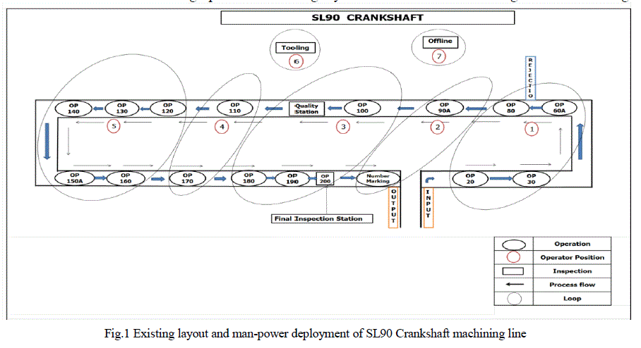
| SL90 Crankshaft machining line consisting total eighteen machines.There are total eight operators per shift. Distribution of operators like 5-online,2-offline and 1-absentism. Arrangement of machine positions in such way that workers perform minimum movement during operation. Existing layout of Crankshaft machining line shown in Fig.1 |
 |
| C. Data Collection of SL90 Crankshaft Machining Line |
| Primary data is collected from actual machining line by document analysis, observations etc. Data used in this work are various variables such as cycle time, standard output. For existing work element, data are to be collected using video camera and stop watch. Sequence of operation, time required to move from one machine to another machine is calculated by using video camera. Stop watch is used to take machining time and offline activities time, which is useful for time study. |
| By using time study, idle time as well as waiting time can be easily calculated. After data collection, the whole activities are split into small activities like take a crane, pick crankshaft, move and load crankshaft etc. with their time and machining time also. Time study gives total time required to perform each activity during process. |
| D. Standardized Work Combination Table |
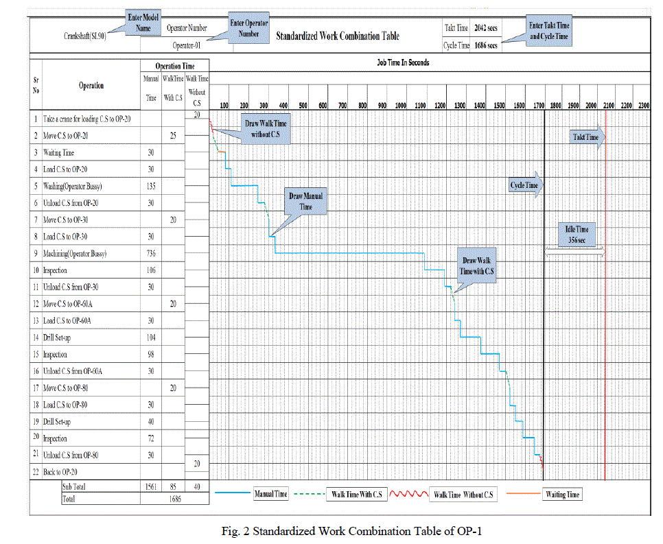
| Standardised work combination table is an important tool, which help to analyse the existing operational activities during actual process. After data collection through time study each big activities split up into small activities including value-added activities and non-value added activities like loading and unloading of crankshaft, TA walk with crankshaft and TA walk without crankshaft are noted with their corresponding time. Then draw chart as per standardized table format shown in Fig.2 Standardized work combination table shows engage time, idle time and waiting time are calculated. |
 |
III.PROCESS FLOW ANALYSIS RESULTS |
| A. Problem Solution |
| From analyzed results of existing SL90 Crankshaft machining line, we come to conclusion that: |
| 1. Online TA idle time is more =80 minute per shift |
| 2. Online TA waiting time is more =35 minute per shift |
| 3. Line is more imbalance |
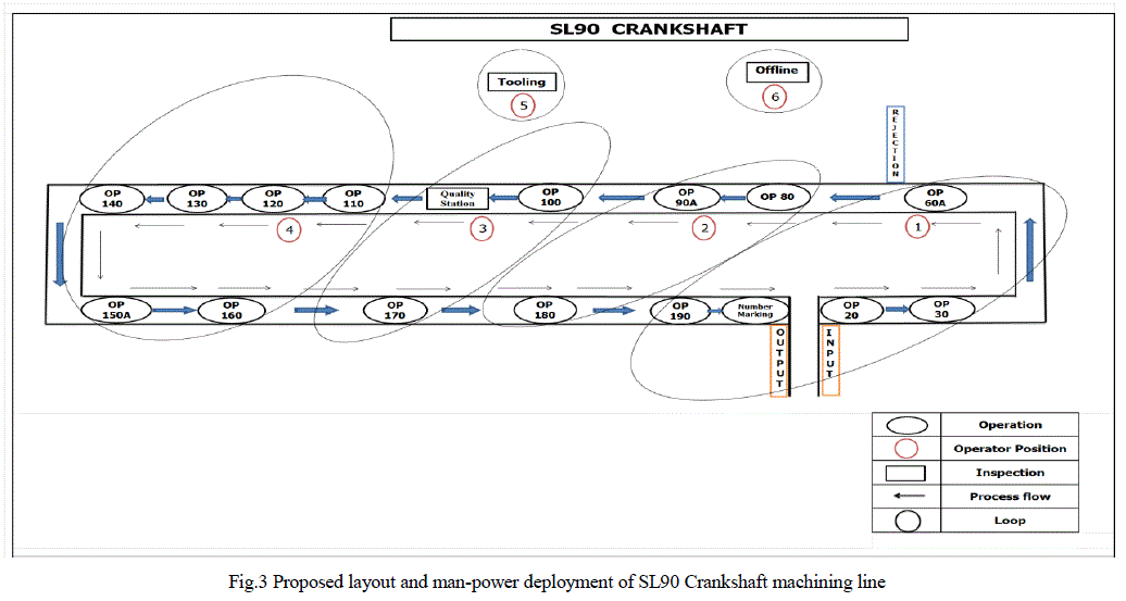
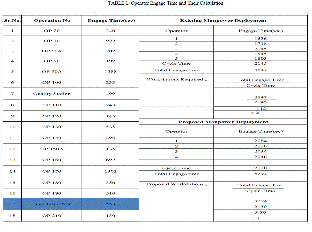
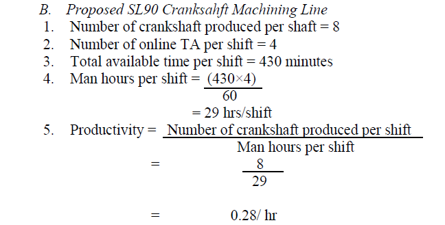
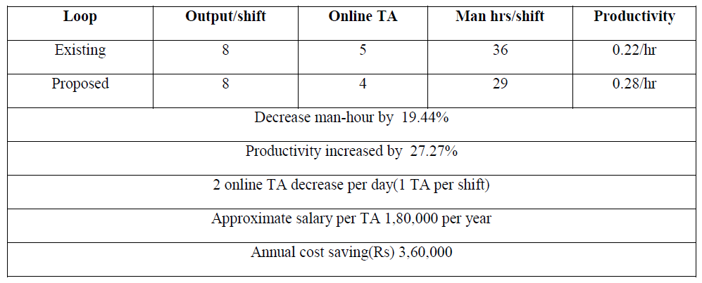
| Final inspection not necessary because after each station there is proper inspection. To find out optimal solution for above problem use Heuristic method. According to this method number of iteration done and finally come to the conclusion reduction of online operators from 5 to 4 with satisfactory balance line.The proposed layout and man-power deployment of SL90 Crankshaft machining line shown in Fig.3.For proposed man-power deployment, time study and motion study results shown in table 1 |
 |
 |
III. RESULTS AND DISCUSSION |
| The results are obtained with the help of Time Study andStandardized Work Combination Table |
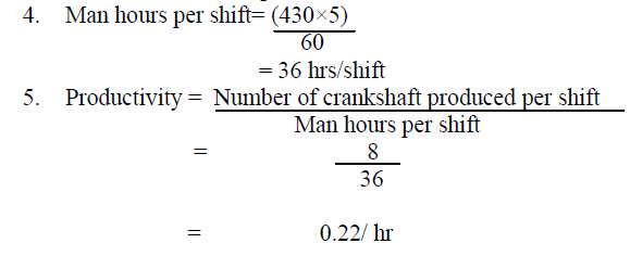
| A. Existed SL90 Cranksahft Machining Line |
| 1. Number of crankshaft produced per shaft=8 |
| 2. Number of online TA per shift=5 |
| 3. Total available time per shift = 430 minutes |
 |
 |
 |
V. CONCLUSION |
| 1. Online TA reduced by 1 i.e. from 5 to 4 no’s without changing output per shift. |
| 2. Online TA idle time reduced by 51 minute per shift, i.e., from 80 to 29 minute per shift. |
| 3. Online TA waiting time reduced by 24 minute per shift, i.e., from 35 to 11 minute per shift. |
| 4.Man-power deployment is approximately balanced. |
VI. SCOPE FOR FUTURE WORK |
| Following are some issues which can be part of future work: |
| 1.For scheduling of raw material as well as finished product, analysis technique can be used. |
| 2. Comparison of this technique with other waste reduction techniques can also be made. |
| 3. It is however to be noted that there is increased in movement of TA during working time on machining line because of reduction in quantity of worker. So, study of ergonomics for comfort of TA is necessary. |
References |
|