ISSN ONLINE(2278-8875) PRINT (2320-3765)
ISSN ONLINE(2278-8875) PRINT (2320-3765)
| R.VinuRashini PG scholar, Dept. of EEE, Velammal Engineering College, Chennai, India |
| Related article at Pubmed, Scholar Google |
Visit for more related articles at International Journal of Advanced Research in Electrical, Electronics and Instrumentation Engineering
The Aim of this project is for protecting the Boiler Feed Pump failure and using a changeover scheme by monitoring the required parameters using pc for the continuous power generation. The existing system in Thermal Power Plants uses the hardware based input and output modules for the protection of Boiler Feed Pump. The major disadvantage of this system is more complicated hardware and many relays are employed. Therefore the changeover of one Feed Pump to another Standby Feed Pump during the emergency situation takes more delay. To overcome this serious problem, the proposed system uses the Pc for Boiler Feed Pump Protection and changeover scheme. In this proposed project the sensing devices such as pressure flow, temperature etc are connected to the ADC and the converted signal is given to the Pc through printer port for monitoring. The computer display all the parameters of Boiler Feed Pump graphically and sends a trip signal to trip the Feed Pump through specially designed fast acting drive circuits when abnormal occurs in any one parameter of Boiler Feed Pump.
Keywords |
| Boiler feed pump, Generator, Turbine, Cooling tower. |
INTRODUCTION |
| The “Ennore Thermal Power Station” is located at Ennore. This power plant supplies most of the generated power to the Chennai city. It is actually a base load power plant. It uses coal as the major fuel. The total capacity of the power plant is 450 MW. |
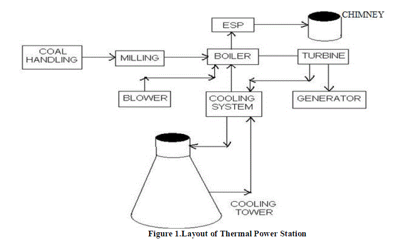 |
| The figure 1 shows the general layout of existing power station. Themain building blocks of a thermal power station are as follows: |
| • Coal Handling |
| • Boiler |
| • Cooling system |
| • Ash Handling |
| • Turbine |
| • Generator |
| • Fuel |
BOILER DESCRIPTION |
| Boiler is the major component for power generation in all the power plants. In thermal power plant the boiler uses the coal as a fuel for producing heat energy which in turn is converted as a mechanical energy by the turbine and the generator generates the electrical energy by converting the mechanical energy. The water is the working fluid, which is used to produce steam for power generation .The water is supplied to the boiler from the tank through the pumps which are commonly known as boiler feed pumps. |
| A. Boiler Feed Pump: |
| In all the thermal power plants each boiler consists of two feed pumps. They are horizontal barrel type installed at ‘0’ meter turbine hall. One pump is required for full load while the other pump is 100% stand by. The feed pump is driven by an electric motor through step up gearbox and hydraulic couplings. Feed water pumps range in size up to many horsepower and the electric motor is usually separated from the pump body by some form of mechanical coupling. Large industrial condensate pumps may also serve as the feed waterpump. Steam and steam engines used on ships and stationary applications such as power plants also require feed water pumps. In this situation, though, the pump was often powered using small steam engine that ran using the steam produced by the boiler.The Functions of Boiler Feed Pump are as follows: |
| During normal operation of the unit, the BFP has to handle the hot water received from feed tank enhancing its positive suction pressure and deliver water with high pressure to boiler drum through HP heaters and economizer. Feed water discharged from the BFP is also used for the following |
| 1. For temperature control of super heated steam. |
| 2. For temperature control of reheated steam. |
| 3. For temperature control of steam after HP by pass. |
| Starting Up Of Boiler Feed Pump |
| 1. Open the BFP motor air cooler valve and ensure adequate flow to the motor air coolers by the pressure gauge provided. Water pressure at the pressure gaugeshould be around 2.5 Ksc. |
| 2. Start the BFP at local and ensure PLOP has cut off, if not stop the PLOP at local. |
| 3. Check the following |
| a. Suction pressure |
| b. Delivery pressure |
| c. Hydraulic disc leak off pressure. |
| d. Lube oil pressure. |
| e. All bearing temperatures. |
| 4. Start one Hydrazine dozing pump and open the delivery valve and connect it to the suction of the feed pump. |
| 5. Check and ensure the BFP is running normal with the above parameters within the limits, without any abnormal vibration by hand touch and abnormal sound. |
| 6. Ensure no oil leaks and feed water leaks from flanges and pump casing etc. |
| 7. After informing OD/Boiler open the delivery by pass valve and feed to the boiler. |
| 8. At 40 MW load close the RC valve and put the other stand by BFP in auto mode as detailed below. |
| Stopping Of BFP: |
| 1. Unload the BFP gradually by reducing the flow and scoop position. |
| 2. At a load current of around 150 amps open the RC valve and gradually closethe delivery valve maintaining the delivery pressure. |
| 3. Stop the BFP and ensure the PLOP cuts in. |
| 4. Close the motor air cooling valve. |
| B. Boiler Feed Pump Protection: |
| Boiler feed pump protection is checked with the help of Instrumentation staff for which the HT breaker should be racked out and kept in test position and dc kept on and ready start permissive indication available at local BFP panel and at UCR. Make the trip protection leads of different protections and see that the ready start permissive vanishes. |
| 1. Motor free end bearing temperature high trip : 80°C. |
| 2. Motor coupling end bearing temperature high trip : 80°C. |
| 3. Pump coupling end bearing temperature high trip : 80°C. |
| 4. Pump free end bearing temperature high trip : 80°C. |
| 5. Thrust bearing temperature high trip : 80°C. |
| 6. Working oil temperature high trip : 130°C. |
| 7. Low lube oil pressure trip : 0.85 Ksc. |
| 8. Hot air temperature high trip : 80°C. |
| 9. Feed pump delivery temperature high trip : 180°C. |
| 10. High hydraulic disc pressure high alarm trip : 12Ksc. |
| C.Existing System: |
| In the existing system, Boiler Feed Pump protection is achieved with the aid of protective devices which are connected to the hardware based input and output modules and dedicated EPROM based processor module. Processor module consists of EPROM, which contains hex coded instructions to carry out Boiler Feed Pump protections. |
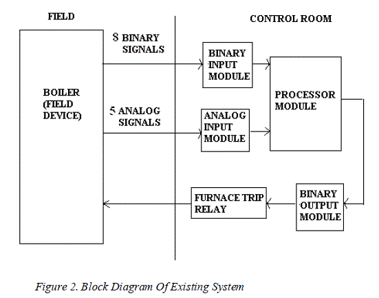 |
| The figure 2shows the existing system which consists of the analog input modules EA 01, EA 02, EA 03 and EA 04, binary input module and the processor module. The hardware modules remain fixed in the control room. |
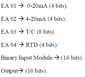
| The ranges of the existing hardware modules are as follows: |
 |
| A 16 bit PR 05 processors used in the thermal power plant. The monitoring program is stored in the processor in hex code format. The output of the processor actuates the furnace trip relay, which opens or closes the main control valve. |
| D.Proposed Project: |
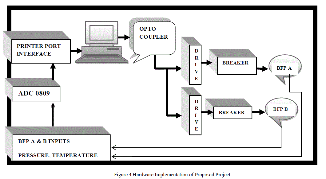
| In this project it is proposed to connect the sensing devices such as pressure, flow, temperature etc to the analog to digital converter after modifying the above signals to the acceptable form by the ADC. The digital signals from the ADC are given to PC through printer port.Computer display graphically all the parameter of Boiler Feed Pumps and sends trip signal to trip the Feed Pump through specially designed fast acting drive circuits when abnormal occurs in any one parameter of Boiler Feed Pump. |
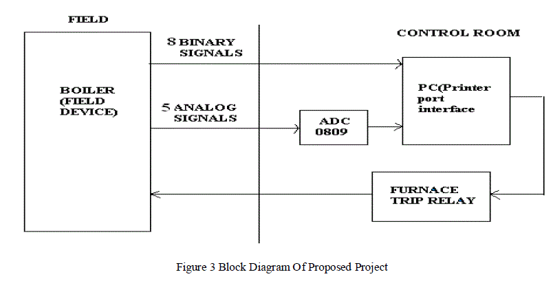 |
| The figure 3 shows the block diagram of proposed project in which the existing hardware relay logics are replaced by the PC controlled one by which the unwanted delays can be avoided. The binary signals that coming from the boiler (field device) is the start or stop signal for the pump. |
| The analog signals that are coming out from the boiler are: |
| a) Delivery Water Pressure |
| b) Suction Water Pressure |
| c) Lube Oil Pressure |
| d) Working Oil Temperature |
| e) Motor Break Oil Temperature |
| f) Delivery Water Temperature |
| g) Suction Water Temperature. |
| The processor module of the original system is replaced by the personal computer. The analog input signals are analyzed after conversion to digital signals by ADC0809. The analog and digital signals are interfaced to the computer via the parallel port interface. The parallel port communication is preferred for its speed of operation. The various input signals of the boiler furnace and its drum level are monitored through the DB-25 Female and Male connectors. On analyzing, the various possible conditions for monitoring the boiler operations are as follows. |
| E. Hardware Implementation of Proposed Project: |
| In our proposed method the boiler pump indications are graphically viewed and are adjusted using the analog and binary simulation board.The digital signal coming out from the PC after processed by the software installed, drives the required pump and protects the boiler shut down. This changeover scheme is useful for the uninterrupted power generation. |
 |
| Signalsconsidered for the boiler feed pump: |
| 1. Feed Pump Delivery Pressure. |
| 2. Feed Pump Working Oil Temperature. |
| 3. Feed pump Bearing Temperature. |
| 4. Feed Pump Lube Oil Temperature. |
| 5. Motor Winding Temperature. |
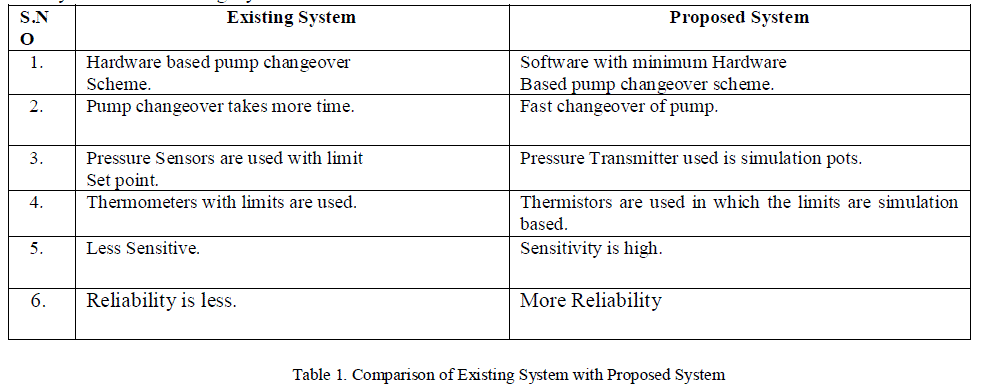
| Proposed System over Existing System: |
 |
| F. Boiler feed pump indication: |
| The Boiler feed pump indication is used to indicate any fault that occurs in the following specifications: |
| h) Delivery Water Pressure |
| i) Suction Water Pressure |
| j) Lube Oil Pressure |
| k) Working Oil Temperature |
| l) Motor Break Oil Temperature |
| m) Delivery Water Temperature |
| n) Suction Water Temperature. |
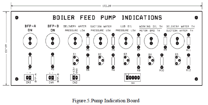 |
| The feed pump indications which consist of 7 led’s in which 5 is used to Indicate any fault that occurs in the specified parameter’s values and 2 is used to Indicates the pump which is currently working. The led’s used is of the range 10mm .The Values for the parameters are fixed using the software and the fault that occurs in any of the parameters, trips the pump which is indicated by the led. |
 |
| Power Supply Parameters: |
| Input supply: 230V ac supply |
| The power requirement for the system is |
| • 5V dc for analog and binary simulation port. |
| • 12V dc for relay circuits. |
| • It comprises of a transformer to step down the 230V a.c. voltage to 15V a.c. voltage. |
| • Fixed voltage regulator IC’s 7805 and 7812 to convert the 15V a.c. voltage to 5V and 12V voltage respectively. |
| • 5V connections are given to analog & binary simulation ports respectively as shown in the figure 4.1 |
| • Transformer rating is 230/12V, 2A. |
RESULT |
| The Protection of boiler feed pump is achieved by updating the working parameters condition using the Pc for continuous power generation. The graphical display of PC based boiler feed pump protection is shown below: |
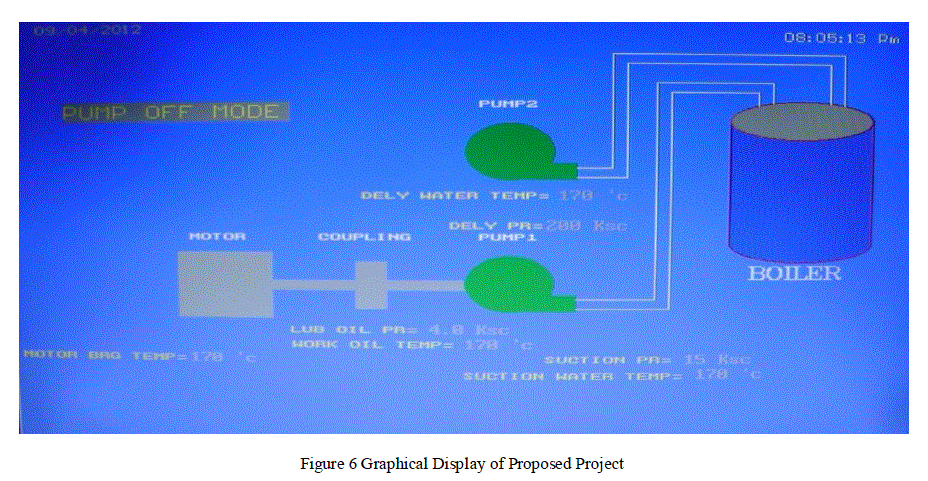 |
| Changeover of one Feed Pump to another standby Feed Pump using this proposed model takes less delay and helps in the emergency period and avoids the boiler shut down and provides continuous power generation. |
CONCLUSION |
| All existing protection circuits are relay based and involve timer units, hence, there is an inherent time delay and increased failure rate .By introduction of soft-based logics the protection circuits are made more reliable and are easy to modify. By introducing the PC based protection the chances of false tripping may be avoided. Also fault tracing is made easy by the soft-based logics as it uses the concept of ‘0’ or ‘1’.Hard timers have their own limited range of operations whereas through PC based protection any range of time delay can be achieved. All the logical operations are achieved through programming which is easy to understand and modify as and when required. The concept of introducing PC based control is to identify and to have continuous monitoring of signal status by introducing graphics. Visualization gives the faulty signal status for identification much faster. |
FUTURE SCOPE |
| The future scope of the project is that the current technique used for the protection of the boiler in the power plant can be evolved to protect the entire power plant as a whole. This may include the main assets of the power plant such as the turbine, generator etc. This advancement can be achieved if separate signals are sensed from each part of the power plant and are accordingly checked and the power plant is safeguarded from the failures automatically. |
References |
|