ISSN ONLINE(2278-8875) PRINT (2320-3765)
ISSN ONLINE(2278-8875) PRINT (2320-3765)
Puladasu Sudhakar1, Dr.Sushama Malaji2, Dr.B.Sarvesh3, U.Lilly Rose 4
|
| Related article at Pubmed, Scholar Google |
Visit for more related articles at International Journal of Advanced Research in Electrical, Electronics and Instrumentation Engineering
This paper mainly deals the impact of relays on feeder protection also different factors used to control the active power, reactive power, power reversals, fault current magnitude and balancing condition of power system to protect the distribution system. when Distributed Generation sources are integrated in to the grid above all problems are occurs along with the feeder voltage regulation and feeder protection for effective operation of DG connected Distribution networks needs control the above factors for this Solid Oxide Fuel Cell (SOFC) is modeled and integrated in to the grid, Rectifier inverter pair (PCU) is consider for controlling the all factors to give protection, simulation are performed using Matlab/Simulink.
Keywords |
| Active Power, Distributed Generation, Power Conditioning Unit, Reactive Power, Solid Oxide Fuel cell, Protection. |
INTRODUCTION |
| This Paper presents a literature review on the impacts of DGs on the distribution network performance. Its starts with an introduction on the structure of distribution networks and the concept of distributed generation. The chapter then focuses on the impact of DGs on the feeder voltage regulation during different operating conditions. Lastly, a detailed explanation on the impact of DG on the feeder protection is presented. |
A. Literature Review |
| Today’s power system is a complex interconnected network that can be subdivided into four major parts: generation, transmission, distribution, and loads. In the generation phase, electric power is generated at 11-30 kV via large central generators located in remote areas. The purpose of the overhead transmission network is to transfer electric energy from generating units at various locations to the distribution network. The distribution network is a medium to low voltage network that is connected to a high voltage transmission network through “step down” transformers. Each transformer feeds power to a number of feeders to which customers are connected either directly or through a distribution transformer which further steps down the voltage to the utilization level, 120 volts for household appliances. |
B. Distributed Generation |
| The term “DISTIBUTED GENERATION” or DG, refers to the small-scale generation of electric power by a unit sited close to the load being served. DG technologies range in size from 5 KW to 10MW The generators are mainly designed to be connected directly to the distribution network near load centers. |
C. Impact of DGs on Distribution Networks |
| The distribution network was designed to extract power from the transmission network and distribute it to the loads. It was not designed to have generators directly connected to it. The distribution network topology, control, and protection are all designed assuming that power is flowing in one direction, from transmission to loads. The connection of DGs to the feeders of the distribution network can cause the power flow to be bi-directional instead of unidirectional affecting the network performance and stability in a number of ways. Through an extensive literature review, all suggested implications for connecting DGs to distribution networks have been studied. The most serious impacts that could not be resolved using conventional techniques were found to be Inverter the impact of the DG on both the feeder voltage regulation and the feeder protection. In the following two subsections, these two implications will be discussed in more detail. |
IMPACT OF DG ON FEEDER VOLTAGE REGULATION |
| When a DG is connected to a feeder, it will affect the voltage regulation of the feeder depending on the location, size, and operating scheme of the DG. In the following section, the conventional voltage regulation will be discussed, followed by the impact of the DG’s presence on such voltage regulation technique. |
A. Conventional Feeder Voltage Regulation |
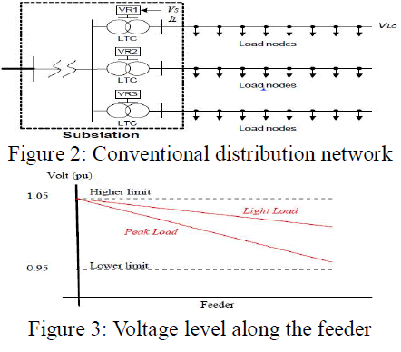
| A distribution network consists of a number of substations which steps down the voltage level and feeds a number of feeders. As shown in Figure 2, the feeder starts from the substation bus and loads are tapped off at every node. Each feeder is equipped with a HV/MV on-load tap changing transformer that has the ability of changing the voltage level of the feeder at the substation bus. The voltage drop along the feeder depends on the feeder loading as illustrated in Figure 3, where the maximum voltage drop occurs during peak load. The on-load tap changing transformer (LTC) and its associated voltage regulator (VR) regulates the voltage at the substation end to compensate for the voltage drop due to the change in loading. The aim is to always keep the voltage along the feeder within ± 5 percent of the nominal voltage. |
 |
VR CONTROL WITH LINE-DROP COMPENSATION: |
| The aim of line-drop compensation is to keep the voltage constant, not at the feeder’s substation bus, but at some remote load center. Normal practice is to sense the load current (local to the transformer) and use this to estimate the voltage drop on the feeder at the remote load center according to the following equation. |
 |
| Where IL = load current, VS = substation bus voltage, and VLC = voltage required at the remote load center. Reset and Xset inside the relay are adjusted to correspond directly to the feeder’s impedance. Thus the substation bus voltage is adjusted to insure that the remote load center voltage is within acceptable limits. |
B. Impact Of Dg On Feeder Voltage Regulation |
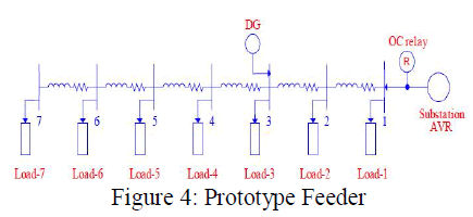
| The following two subsections illustrate the impact a DG has on the feeder voltage regulation under two conditions, normal and emergency. To demonstrate such conditions, a seven node prototype feeder (Figure 4) is simulated under different scenarios. The feeder load is assumed to be equally distributed along the feeder, and the feeder is protected with an OC relay. (Relevant data in Appendix A) Volt (pu) |
 |
A) Impact of Dg on the VR During Normal Operation |
| As previously indicated, in a conventional feeder the voltage level is regulated by the VR, which estimates the voltage drop over the feeder by measuring the feeder current at the substation end. However, this depends mainly on the simple fact that the power is unidirectional from the substation bus (where the VR is located) flowing into the end of the feeder. The presence of DGs makes the power bi-directional, and if the DGs connected to a feeder are carrying most or all the feeder load, then the voltage profile along the feeder depends mainly on the DGs’ location, power generated, and the DG power factor. This Creates an unpredicted and uncontrolled situation where the voltage level of all nodes might or might not be within acceptable limits. To illustrate such a problem, consider the prototype system in the following three scenarios: |
| Case 1: feeder without DGs and the voltage along the feeder is within acceptable limits. |
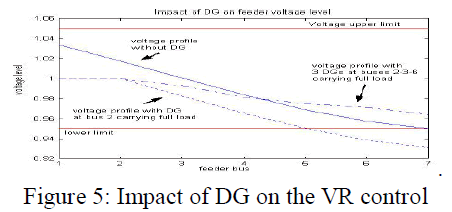
| Case 2: feeder with three DGs at nodes 2, 3, and 6 carrying the whole feeder load. |
| Case 3: feeder with one DG at node 2 carrying the whole feeder load. |
| Figure 5 shows the voltage profile along the feeder for the three different cases. For cases 2 and 3, the current flowing from the on-load-transformer is almost zero. The VR will assume that both cases are the same with the feeder’s load at the minimum level, therefore it will adjust its voltage level to 1.00 p.u. The voltage profile in case 2 is within the limits because the DGs are distributed along the feeder, unlike the third case, where the feeder loads are carried by a localized DG. This shows that, although the VR treated both cases similarly, the voltage profile along the feeder is totally different and depends on the number and location of the DGs carrying the load. It could now be concluded that the conventional VR technique cannot properly adjust the voltage level of a feeder with various DGs connected to it, since it depends solely on measuring the feeder’s current at the substation end, which is no longer a good indication of the feeder status. Therefore, a new technique must be developed to facilitate the coordination between DGs and the VR for better feeder voltage regulation |
 |
| B) Voltage Regulation Under Emergency Conditions Of Sudden Disconnection Of ADG |
| If the DG connected to a feeder operates without considering the impact of its operation on its neighboring nodes, one potential problem that may arise is that the sudden disconnection of a DG may cause an undesirable tripping of other generators connected to the same feeder. The location of the DG, the feeder loading, and the DG power generated are key factors in the impact of the sudden disconnection of that generator. |
| To illustrate this potential problem, consider the prototype system with a DG connected to node three and operating at its maximum capacity carrying 30 percent of the total feeder load. The solid curve in Figure 6 represents the voltage profile along the feeder with the DG connected. The effect of suddenly disconnecting this DG is shown in the lower curve, where the voltage level of the last portion of the feeder (around 40 percent of the feeder length) falls below the lower permissible limit. This will trigger the under voltage relay protecting the DGs located in this portion of the feeder to trip. Although the VR will adjust the feeder voltage level (upper dashed curve), its slow response time will make its action |
| Use less. The VR takes about 10 seconds to move one tap which corresponds to about 0.05 pu voltage change (assuming a 16 tap VR for ±5 percent voltage regulation) On the other hand, the DGs are quite sensitive to voltage sags, as they usually employ under voltage/overvoltage protection schemes to protect the device against the external faults. These protection schemes are usually fast, typically set to trip the DG within two seconds if the voltage level is below the acceptable limit, and trip within 0.16 seconds if the voltage level is less than 50 percent of nominal voltage. Therefore, the VR cannot provide the quick voltage support needed to restore the voltages following a sudden disconnection of the DG, because the response of the VR is much slower than needed. |
 |
IMPACT OF DG ON FEEDER PROTECTION |
| DG presence in a distribution network impacts the conventional feeder protection schemes. In the following two sections, we will discuss how the feeder is currently protected and the impacts of DG presence on such protection schemes. |
A. Conventional Feeder Protection |
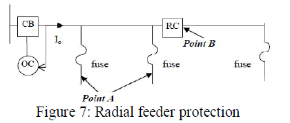
| Distribution feeders are usually radial with the loads tapped off along the feeder sections. The feeder protection strategy aims at optimizing the service continuity to the maximum number of users following a fault disturbance on the network. This means applying a combination of circuit breakers, automatic reclosers, and fuses to clear temporary and permanent faults. As shown in Figure 7, fuses are responsible for isolating permanent faults at point A and beyond. The automatic re-closer clears faults on point B and beyond (it’s downstream). The main circuit breaker at the beginning of the feeder is equipped with an OC relay to isolate any permanent fault along the main feeder. When the feeder current exceeds a certain pickup value, the OC relay sends the breaker a trip signal, and the speed of tripping the fault is inversely proportional with the fault current magnitude. |
 |
| B. Impact Of Dg On Feeder Protection |
| The conventional protection scheme of each feeder is designed, assuming the feeder is radial. But, as mentioned earlier, the presence of DGs on a feeder will cause bi-directional power flow, which means that part of the feeder will no longer be radial. This will create several problems to the current protection schemes used, Ackermann in shows that the presence of DGs will result in an increase in fault current levels, and that the detailed assessment of the impact DGs might have on fault currents is very challenging as the impact largely depends on a number of factors. Among these are “the technology of the DG, its operation mode, interface with the DG, system voltage prior to fault, etc…” In, Gomez claims that there is no concern with the fuse. |
| DG when its power is less than 10 percent of the minimum load demand by the feeder. The most immediate consequence is the need for verification of the protective device breaking capacity, which might not be enough due to the increase of the available short-circuit power. As mentioned by Barker in the fault contribution from a single small DG unit is not large, however, the aggregate contributions of many small units, or a few large units, can alter the short circuit levels enough to cause protective devices to malfunction. The main impacts of DG on the feeder protection connection are in three different areas: the OC relay performance, the re-closer operation, and the islanding protection. |
A) Over-current relay performance |
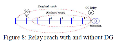
| One of the DG impacts on feeder protection is on the OC relay, as the current contribution from the DG will affect the “reach of the relay”. OC relays are set to protect a certain part of the feeder, which is sometimes referred to as the “reach”. The reach of the relay is determined by the minimum fault current it is set to react to, the so-called pick-up current. The presence of a DG will reduce the reach of the OC relay [Dug02], thus leaving medium impedance faults at the end of the feeder undetected (Figure 8). The reduction in reach is due to the fact that the DG contributes to the fault current, thus decreasing the fault current seen by the OC relay for the same fault resistance (Rf). To understand the effect of DGs on reducing the reach of the feeder’s OC relay, The influence of the DG’s location and power level on the relay effectiveness is also shown. Moreover, a method designed to mitigate the problem is presented in the same chapter. |
 |
B) Re-closer operation |
| The DG contribution to feeder faults impacts the operation of the re-closer in three different ways: |
| 1) the re-closer might be exposed to high mechanical and thermal stresses beyond its rated limits, |
| 2) the re-closer-fuse coordination can be affected, and |
| 3) the re-closer might trip for upstream faults. In the sections below, we will discuss these impacts in more detail. |
1) Exposing the re-closer to high mechanical and thermal stresses [Doy02] |
| Re-closers are designed to withstand and interrupt the high fault currents. One of the important parameters of a recloser is the maximum current the re-closer can withstand. This is called the maximum withstand current. With DGs connected as shown in Figure 9, the fault current seen by the re-closer (IRC) will increase. This would not normally cause a problem as long as the new IRC does not exceed the re-closer maximum withstand capability. However, if IRC > Imax the re-closer will be exposed to mechanical and thermal stresses, especially in the first one and a half cycles, which might cause a re-closer failure. |
 |
2) Re-closer-fuse coordination |
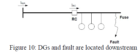
| The philosophy of feeder protection is that a fuse should only operate for permanent faults within its reach. But for temporary faults, the re-closer should disconnect the circuit with fast operation and give the fault a chance to clear. Only if the fault is permanent, should the fuse be allowed to open. As mentioned by, for the feeder topology as the one shown in Figure 10, the fault current flowing through the fuse is greater than that flowing through the re-closer. This might cause the fuse to trip faster than the re-closer for temporary faults. And since temporary faults account for 70 to 80 percent of feeder faults, the miss coordination between fuse and re-closer will impact the feeder’s reliability considerably. Another condition that may cause the fuse to trip faster than the re-closer under temporary Faults were presented. As suggested in , if DG units are added to the feeder topology shown in Figure 9, the fault current may become large enough that the lateral fuse no longer coordinates with the feeder circuit breaker during faults. This would lead to unnecessary fuse operations. Points out that it is very likely that coordination between the re-closer and any down-line fuses will be lost. Because both the re-closer and fuses operate faster at higher fault currents, the required margins between the re-closer fast curve and the fuse minimum melt curve could be reduced enough to lose coordination. |
 |
3) Re-closer tripping for upstream faults [Doy02] |
| When there are DGs downstream of a re-closer as illustrated in Figure 11, then the re-closer will see fault currents in the reverse direction, if the fault is upstream of the re-closer. It may even be possible that the IRC exceeds the minimum tripping value of the re-closer, and thus the re-closer will trip for faults upstream, which is unacceptable. |
 |
| The solution for the re-closer tripping problem for upstream faults can be achieved by upgrading the re-closer’s conventional OC relay by a directional OC relay. This will make the re-closer trip only if the IRC exceeds the minimum tripping value in a certain direction. While solving the first two problems (1 & 2) related to the re-closer operation is not that simple, the solution involves estimating the contribution of the DG into the fault current. This fault current contribution is needed to properly size re-closers and correctly set the re-closer-fuse coordination parameters. Ackermann agree that the only accurate approach for solving such problem is to perform a software-based analysis, which correctly models the DG behavior to fault events. Therefore, relatively accurate short-circuit models of different types of DGs are needed to assess the impact of its fault contribution during the time frame from about one-cycle up to several seconds into a fault event. Chapter 5 presents a technique that was developed to facilitate the integration of inverter interfaced DGs into conventional fault analysis studies of distribution networks. |
C) Islanding protection |
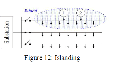
| Islanding on a feeder occurs when a protection device – breaker, fuse or an automatic re-closer – isolates a section of the feeder to isolate a fault, thus creating an island. Islanding becomes a concern when there is a DG on the islanded part of the feeder, as the DG will try to energize the island (Figure 12). Due to the serious problems of islanding, which includes threatening the safety of utility repair personnel, utilities and standard19 making bodies require that DGs be equipped with anti-islanding protection, so DGs that are on the islanded part of the feeder can be disconnected as soon as possible. |
 |
| show that none of the current islanding detection methods are capable of detecting the island under all possible conditions. The main reason for such a drawback is that the current methods use only their local measurements, such as the DG’s voltage and current. For protecting the feeder at all conditions, further research is needed to either develop a new technique or improve the current techniques. Although islanding protection is not one of the problems his dissertation focuses on, it was presented to show that the islanding protection can be addressed more effectively once a communication network is adopted at the distribution level, the same communication network that is needed for addressing the problems associated with integration of DG into distribution network. |
SOFC BASED DISTRIBUTED GENERATION |
| Fuel cell stack control is achieved mainly by adjustment of the input volume of gas air to control real power output. Since Fuel cells generate DC power, they must be connected to the AC power distribution system via DC/AC inverters which can control the tracking of real and reactive power set points and to adjust the power factor of a fuel cell plant Desirable inverter characteristics include: reliability and efficiency and have capability to adjust power factor while maintaining low line-current distortion. Pulse Width Modulation Voltage Source Inverters (PWM_VSI) fulfills these requirements. |
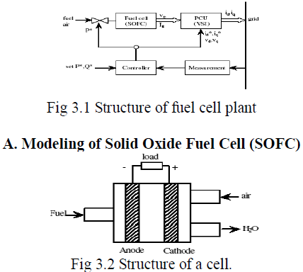 |
| The SOFC consists of hundreds of cells connected in series and in parallel. Fuel and air are passed through the cells. By regulating the valve, the amount of fuel fed into the fuel cell stacks is adjusted, and the output real power of the fuel cell system is controlled. |
| The Nernst’s equation and Ohm’s law determine the average voltage magnitude of the fuel cell stack. The following |
| equations model the voltage of the fuel cell stack: |
 |
| Where: |
| N0 is the number of cells connected in series; |
| E0 is voltage associated with the reaction free energy; |
| R is the universal gas constant; |
| T is the temperature; |
| Ifo is the current of the fuel cell stack; |
| F is the Faraday's constant. |
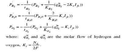
| PH2 PH2O, and P O2 are determined by the following |
| Differential equations: |
 |
B. Modeling of power conditioning unit |
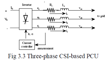
| The output average voltage magnitude is regulated by the DC/AC inverter ignition angle. The action of the power Electronics devices in such an inverter is much faster than the technical valved. Thus, for fast response, DC/AC inverter is the first choice. A dynamic model of current source inverter (CSI) PCU for fuel cell is developed. A three-phase equivalent circuit of PCU is shown in Fig. 3.3. |
| In Fig. 3.3, Rs represents the sum of the losses of the transformer resistance and the inverter conduction, Ls represents the leakage inductance of transformer, ea, eb, ec are the three-phase AC voltage outputs of the inverter, and ia, ib, ic are the three-phase AC current outputs of the inverter. The bus voltages of the grid are vsa, vsb, vsc. They are also represented by a pharos Vs∠Φ. The inputs for inverter are the PWM modulation gain k and firing angle Φ The DC voltage Vfc is the output of SOFC). |
 |
| The differential equations of the three-phase CSI-based PCU are represented |
 |
| WhereP={a,b,c} |
| To develop the dynamic model, the state equations are transformed to the system synchronous reference frame as: |
 |
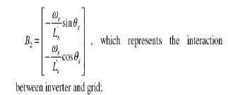
| Where iq and id are the current in q-d reference frame; and |
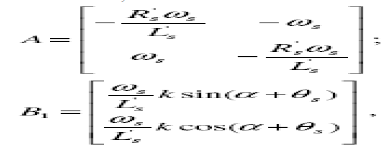 |
| This represents the interaction between inverter and fuel cell |
 |
| In the DC circuit, the relationship between voltage and current may be expressed as: |
 |
C. Modeling of Measuring and control unit |
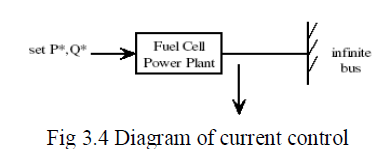
| To implement the control of PCU, the current tracking inverter control strategy is used to track the real power (P*) and reactive power (Q*) requirements, or to track the real power (P*) and voltage (v*) requirements. Thus the fuel cell power plant can be considered as a PQ bus or PV bus depending on the different control strategies. The set point (P*,Q*) is transformed as the current set point (I*q, I* d). ……… (3.7) |
 |
| The current tracking PQ type control strategy is presented in Fig. 3.3. The input values id, iq are compared with references I*d, I*q. The errors are fed into the PI controller and comparator to generate PWM modulation gain k and inverter firing angle |
 |
| The capability of the fuel cell power plant to track real and reactive power is tested in the single DG and infinite bus system. |
 |
| Figures 3.3 & 3.4 show the measured P and Q responses, when the real power set point P* step changes from 0.875 to 0.7 at t = 5.0s and the reactive power set point Q* remains constant. The simulated dynamic responses demonstrate the fast power tracking capability of the fuel cell power plant. |
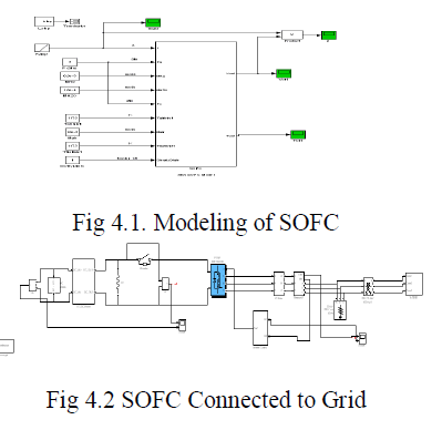
SIMULATION ANALYSIS OF SOFC |
 |
SOFC RESULTS |
| The fuel cell stack consists of 18 cells each cell can produce 25V the total voltage produced by the above SOFC stack is 450V which is as shown in figure 5.1 |
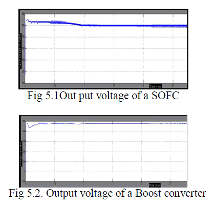 |
| The steady state DC voltage which is produced by the SOFCDG system is shown in the figure5.4.1 in order to attain the reference value of 480V this voltage is regulated by the boost dc-dc converter it is connected in between the SOFC cell and the PWM inverter and boost converter is needed to control the out put voltage of PWM inverter which in terms feeding to the three phase grid. |
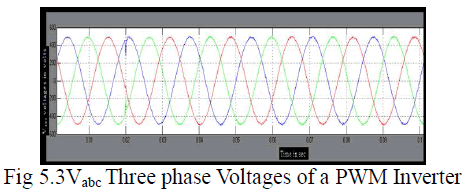 |
| The three phase voltages at the grid are shown in the above figures5.4.3. the controllable DC voltages at the out put of boost dc-dc converter is converted in to three phase AC voltages by three phase two level PWM inverter which is operating in voltage controlled mode. |
 |
| At t=0.02s the three phase circuit breaker which is connected between the three phase load and the inverter terminals is switched ON that’s why before switching on there is no current in the three phase system which is shown in above figure 5.4. |
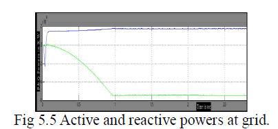 |
| The real and reactive power which are needed by the loads at the grid terminals are presented in the above figure 5.5 most of the loads which are connected in this thesis are of inductive type of loads which needs more reactive power. Due to reactive power consumption in above figure 5.5 reactive power is in negative region. |
CONCLUSIONS |
| This paper focus on the impact of distribution generation on distribution networks and their protection. Its examined the impact of DGs on conventional feeder voltage regulation, under both normal and emergency conditions the different factors used to control the active power, reactive power, power reversals, fault current magnitude and balancing condition of power system to protect the distribution system. SOFC is injected by means of (PCU) all factors are controlled to give protection, simulation are performed using Matlab/Simulink. |
References |
|