ISSN ONLINE(2278-8875) PRINT (2320-3765)
ISSN ONLINE(2278-8875) PRINT (2320-3765)
SM Hunagund1, Thanu shree M2, Rohini GV3
|
| Related article at Pubmed, Scholar Google |
Visit for more related articles at International Journal of Advanced Research in Electrical, Electronics and Instrumentation Engineering
To simulate the targets for the Radar system with respect to the Pulse Repetitive Time (PRT) and further to produce various target scenarios with respect to PRT such as: Speed of the target, Number of targets, Direction of targets. In this project the targets are simulated to efficiently test the functioning of an radar system which is much difficult using an practical targets each time for testing all the functionalities of an radar .This methodology helps us to check the functionality of an radar system in a simpler manner and the features of radar systems can be altered accordingly. A Pulse repetitive time (PRT) module is used to generate the targets i.e. the radar targets are simulated with respect to the PRT.. Counter module is used to control the target parameters such as speed of target, control of target parameters, used to calculate the target distance. The field-programmable gate array (FPGA) is a semiconductor device that can be programmed after manufacturing. Hard intellectual property (IP) blocks built into the FPGA fabric provide rich functions while lowering power and cost and freeing up logic resources for product differentiation.
INTRODUCTION |
| Radar is an acronym for "radio detection and ranging." It is an object detection system that uses electromagnetic waves to identify the range, altitude, direction, or speed of both moving and fixed objects such as aircraft, ships, motor vehicles, weather formations, and terrain. A radar system usually operates in the ultra-high-frequency (UHF) or microwave part of the radio-frequency (RF) spectrum, Radar systems are widely used in air-traffic control, aircraft navigation, and marine navigation.Radar is an electronic system for the detection and location of reflecting objects. The radar antenna illuminates the target with a microwave signal, which is then reflected and picked up by a receiving device. The electrical signal picked up by the receiving antenna is called echo or return.The radar signal is generated by a powerful transmitter and received by a highly sensitive receiver. The duplexer alternately switches the antenna between the transmitter and receiver so that only one antenna need be used. This switching is necessary because the high-power pulses of the transmitter would destroy the receiver if energy were allowed to enter the receiver. |
SIGNAL ROUTING |
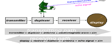 |
| • The radar transmitter produces short duration high-power RF- pulses of energy. |
| • The duplexer alternately switches the antenna between the transmitter and receiver so that only one antenna need be used. This switching is necessary because the high-power pulses of the transmitter would destroy the receiver if energy were allowed to enter the receiver. |
| • The antenna transfers the transmitter energy to signals in space with the required distribution and efficiency. This process is applied in an identical way on reception. |
| • The transmitted pulses are radiated into space by the antenna as an electromagnetic wave. This wave travels in a straight line with a constant velocity and will be reflected by an aim. |
| • The antenna receives the back scattered echo signals. |
| • During reception the duplexer lead the weakly echo signals to the receiver. |
| • The hypersensitive receiver amplifies and demodulates the received RF-signals. The receiver provides video signals on the output. |
| • The indicator should present to the observer a continuous, easily understandable, graphic picture of the relative position of radar targets. |
| • The complete operation of signal routing is shown by the above figure . |
PROJECT BLOCK DIAGRAM |
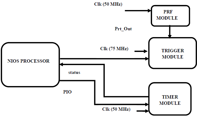 |
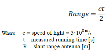
| Pulse repetition frequency (PRF) is the number of pulses per time unit (e.g. Seconds). Waves are thought of as more or less pure single frequency phenomena while pulses may be thought of as composed of a number of pure frequencies. The reciprocal of PRF is called the Pulse Repetition Time (PRT), Pulse Repetition Interval (PRI), or Inter-Pulse Period (IPP), which is the elapsed time from the beginning of one pulse to the beginning of the next pulse. Within radar technology PRT is important since it determines the maximum target range (Rmax) and maximum Doppler velocity (Vmax) that can be accurately determined by the radar.A radar system determines range, shown by range equation, through the time delay between pulse transmission and reception by the relation: |
 |
TRIGGER MODULE |
| The important step in testing RADAR is to generate artificial targets with known parameters and check whether the RADAR provides the same parameter after detection. We test the RADAR with objects (targets) of the following characteristics: |
| • Objects should have linear motion. |
| • Objects should have a constant speed.(max. 1000 m/s) |
| • Objects should be within the range of 90km from the RADAR. |
| • Objects should have an equal spacing between themselves (max. of 5km). |
| • There must be a maximum of 7 objects. More objects shall be added by increasing the size of data bytes used. |
| • It may come towards or go away from the RADAR. |
| • The Trigger width varies depending on the size of the object. |
NIOS II PROCESSOR |
| Nios II is a 32-bit embedded-processor architecture designed specifically for the Altera family of FPGAs. Nios II incorporates many enhancements over the original Nios architecture, making it more suitable for a wider range of embedded computing applications, from DSP to system-control.Nios II is comparable to MicroBlaze, a competing softcore CPU for the Xilinx family of FPGA. Unlike Microblaze, Nios-II is licensable through a third-party IP provider, Synopsys Designware. Through the Designware license, designers can port Nios-based designs from an FPGA-platform to a mass production ASIC-device. The Nios II processor is a general-purpose RISC processor core, providing: Full 32-bit instruction set, data path, and address space; 32 general-purpose registers Optional shadow register sets; 32 interrupt sources; External interrupt controller interface for more interrupt sources; Single-instruction 32 × 32 multiply and divide producing a 32-bit result; Dedicated instructions for computing 64-bit and 128-bit products of multiplication; Floating-point instructions for single-precision floating-point operations; Single-instruction barrel shifter; Access to a variety of on-chip peripherals, and interfaces to off-chip memories and peripherals; Hardwareassisted debug module enabling processor start, stop, step, and trace under control of the Nios II software development tools; Optional memory management unit (MMU) to support operating systems that require MMUs; Optional memory protection unit (MPU); Software development environment based on the GNU C/C++ tool chain and the Nios II Software Build Tools for Eclipse; Integration with Altera's SignalTap® II Embedded Logic Analyzer, enabling real - time analysis of instructions and data along with other signals in the FPGA design; Instruction set architecture (ISA) compatible across all Nios II processor systems; Performance up to 250 DMIPS A Nios II processor system is equivalent to a microcontroller or “computer on a chip” that includes a processor and a combination of peripherals and memory on a single chip. A Nios II processor system consists of a Nios II processor core, a set of on-chip peripherals, on-chip memory, andinterfaces to off-chip memory, all implemented on a single Altera device. Like a microcontroller family, all Nios II processor systems use a consistent instruction set and programming model. The Nios II architecture defines the following functional units: |
| âÃâàRegister file |
| âÃâàInterface to custom instruction logic |
| âÃâàException controller |
| âÃâàInternal or external interrupt controller |
| âÃâàMemory management unit (MMU) |
| âÃâàMemory protection unit (MPU) |
| âÃâàInstruction and data cache memories |
| âÃâàTightly-coupled memory interfaces for instructions and data |
| âÃâàJTAG debug module. |
TIMMER (COUNTER) MODULE |
| In digital logic and computing, a counter is a device which stores (and sometimes displays) the number of times a particular event or process has occurred, often in relationship to a clock signal. In practice, there are two types of counters: |
| • Up counters, which increase (increment) in value |
| • Down counters, which decrease (decrement) in value |
| The Timer or Counter module is employed to ensure continuous simulation process. A handshake operation is performed between the timer module and the NIOS processor. This is done to indicate the end of every clock cycle of 10ms to the processor so it continues with the simulation for the next clock cycle thereby ensuring continuous simulation. |
RESULT |
 |
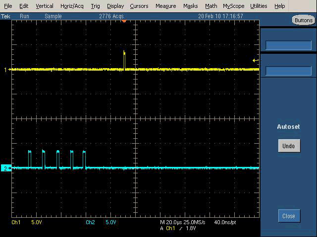 |
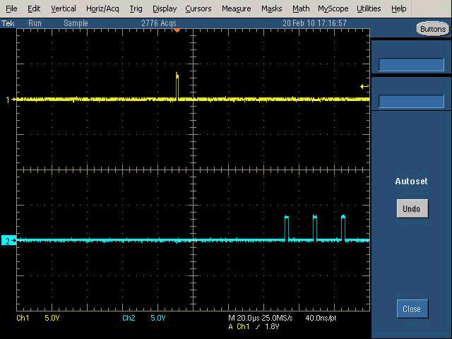
| The output, shown by the figure 8.1, shows the PRT and three Triggers (targets). The PRT waveform in real-time application is taken from the RADAR as it might change for different RADARs. The output, shown by the figures, shows the PRT and three Triggers (targets). The PRT waveform in real-time application is taken from the RADAR as it might change for different RADARs. For the sake of testing of the kit the PRT module is created in the project. |
CONCLUSION |
| The RADAR target simulator was successfully implemented on an Altera Stratix II FPGA kit using VHDL and C programming and Altera Quartus II software. Quartus II software is used because the Stratix II device offers full support only to some of the software tools which consists of Quartus II. This method of realization has helped us to achieve a device that is |
| • Flexible |
| • Customizable |
| • Cheap compared to previous hardware-oriented designs |
| • Fast & |
| • Reliable. |
FUTURE SCOPE |
| • The number of targets can be increased with modifications in the source code and by increasing the data volume handled through out the process. |
| • Spaces between targets can be made unequal and simulation can be performed. |
| • LAN can be used in place of RS232 serial communication. LAN will provide very high speed fast communication between systems as the packet size handled is more than RS232. |
| • The speed of the targets can be made non-uniform. |
APPLICATIONS |
| The system is designed to be easily modified for any other target simulator application or aircraft platform. The unit is compact and lightweight enabling the following applications: |
| • Training Target Simulator |
| • Radar Test Simulator |
| • Self-protection Jamming |
| • Effectiveness Verification |
| • Radar Vulnerability |
| • RF capture for Analysis |
References |
|