ISSN ONLINE(2278-8875) PRINT (2320-3765)
ISSN ONLINE(2278-8875) PRINT (2320-3765)
B.S.D padmaja1, K. Ramakanth Reddy2, J. Anusha3, A. Sarath4
|
| Related article at Pubmed, Scholar Google |
Visit for more related articles at International Journal of Advanced Research in Electrical, Electronics and Instrumentation Engineering
This paper investigated a new windmill shaped Mushroom like structure. The geometry of this artificial magnetic conductor AMC consists similar design as EBG structures but they have cuts on each side of the patch. In this Frequency selective surface this cuts made the appropriate effects in making the antenna as tunable antenna. The design and the results like return loss, gain, E, H fields are presented comparatively with conventional antenna
Keywords |
| Tunable, Energy Band gap, Frequency selectivity, reflecting waves, multi band |
INTRODUCTION |
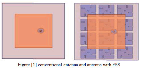
| The AMC have considerable attention in recent years for several applications because of their behaviour of not allowing surface waves [1]. Especially in the last years they are used to design the tunable and steerable antennas for communication systems [4]. To design capable adaptive antennas to achieve selectivity in frequency. Generally these meta-materials have two properties first, they have a forbidden frequency band over which surface waves and currents cannot propagate[2], making them useful as ground planes and planar reflectors or waveguide type filters. For example, antenna ground planes that use these surfaces have good radiation patterns without unwanted ripples based on suppressing the surface wave propagation within the band gap frequency range [1]. Second, AMC surfaces have very high surface impedance within a specific limited frequency range, where the tangential magnetic field is small, even with a large electric field along the surface [2, 3]. Due to these abilities recently they are used in achieving tunable and steerable antennas where the patches are inter connected with variable diode to change C value therefore the tuning band of EBG structure[4]. Now in this paper the multiband antenna can be achieved with tenability by having cuts in patches this new FSS will look like a windmill shape and the rectangular micro-strip antenna with co-axial probe feed works at 2GHz is taken for analysis the antenna and the FSS used as Ground are shown in the following figure [1]. |
 |
BACK GROUND OF THE WORK |
| When the invented meta-materials are used to replace the round plane or reflecting surfaces the main reason to obtain the zero phase reversal [12] of the reflected waves. In antennas concept we know that the space waves from antenna and the surface waves from Antenna ground plane may cause multi-path interference. But these meta-material surfaces will generate zero phase reversal from reflected waves and add them together with space waves resulting in the enhancement of the antenna radiation and directivity. And later n based on this surfaces several researches made possible to enhance the parameters of the antenna. Especially to intervene this concept to obtain adaptive antennas is very interesting theme in research. To obtain the multi frequency operational antenna and to steer the radiation beam into desired region [4]. |
PROPOSED MODEL AND DESIGNING |
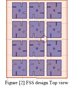
| The model is proposed to obtain the multi band operable antenna without changing the antenna specifications. As we know that the unit cell of conventional EBG unit cell is made of capacitance and inductance combination [13]. Here we use the variation in capacitance as key factor to obtain different frequency of operations. By cutting the metal sheets of EBG cells we can alter the overlapped area by doing so we can be able to change the overlapping capacitance that will make the change in tuning frequency to obtain multi band frequency.The FSS is designed in the same manner as the mushroom like structures which having 2×2×0.001cm patches, via with 0.1cm radius 0.499cm height and cuts of dimensions 0.5×0.1×0.001cm. The gap between the patches is 0.2cm the FSS over view is shown in the figure [2]. |
 |
SIMULATION RESULTS |
| The Proposed model is designed and analyzed by using the HFSS software and the results are presented by comparing the conventional antenna with antenna having the designed FSS as ground plane. |
3.1 Return loss curves |
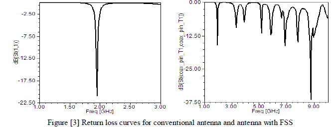
| The return loss curves are presented in the following figure [3]. Where in the first curve it represents the return loss and operating frequency when it is having the normal plane ground but in the second curve we can observe that when the FSS is replaced the ground the antenna can work at multi-band and again it will change to different frequencies by having the variations in cut size. |
 |
3.2 Gain in 2D and 3D |
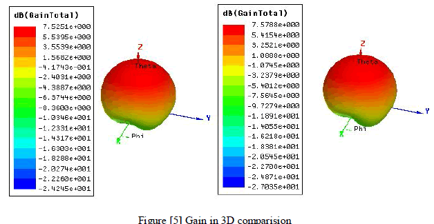
| The comparision of gain in 2D curves and 3D are shown in the following figures [4] and [5]. |
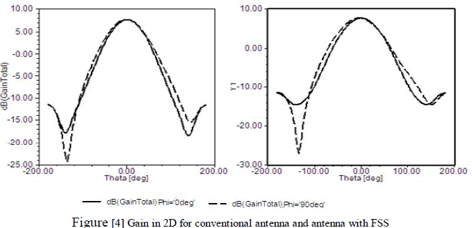 |
| Here the gain enhancement also depends on proper tuning if the cuts are made in improper way then they may caues energy band gap differs where the radiation energy can also gets supressed along with surface wave are in the other hand we can say that it causes propblem that the space wave vector components and the surface wave vector componets will gets cancel each other resulting in poor radiation. |
 |
3.3 E and H field analysis |
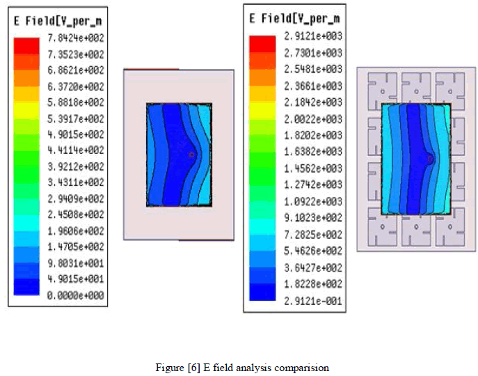
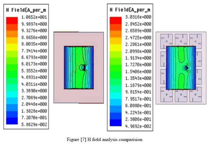
| The E and H field analysis are shown in the figures [6] and [7]. Whre they show hoe the E,H filed distributions are chaned due to the presence of the FSS. |
 |
 |
| TABLE I Antenna Parameters |
| Some other antenna parameters comparison is illustrated in the following table [1]. |
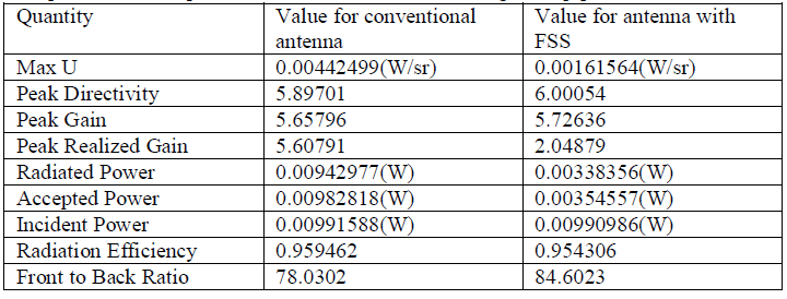 |
| In the above table some other antenna parameters were compared we can clearly see that the parameters are improved we place the FSS. |
CONCLUSION |
| These new AMC surfaces can tune the antenna to work with different frequencies over a selected band. Instead of changing the physical components like variable diodes are having the FET components between the patches of FSS the changing of cuts with movable plates is proposed and results are presented. |
References |
|