ISSN ONLINE(2278-8875) PRINT (2320-3765)
ISSN ONLINE(2278-8875) PRINT (2320-3765)
| W.V.Jahnavi Assistant Professor, Department of EEE, Sree Vidyanikethan Engineering College, Tirupati, A.P. India |
| Related article at Pubmed, Scholar Google |
Visit for more related articles at International Journal of Advanced Research in Electrical, Electronics and Instrumentation Engineering
The Main objective of this paper is to present the reduction of losses and maintain voltage profile constant in Distribution system by implementing HVDS over LVDS. The Overall power losses are mainly classified into Transmission losses, Distribution losses, Theft and billing deficiencies. In India, the total losses account for 32%, in which the Transmission losses share 4-6%, Distribution losses share 15 – 18% and Theft losses share 10-15%. Distribution losses and theft losses are mainly because of transmitting power at low load voltage profile to more number of consumers using High rating kVA Transformer. In case of LVDS, as more number of customers are given supply from high rating kVA transformer, as in case of any failure, more number of consumers will be affected . But in case of HVDS, less number of customers is connected to low rating kVA transformer, so, less number of customers will affect at failure. In this paper, MATLAB simulation is applied to Distribution System before implementing HVDS and after implementing the HVDS. The Voltage profiles and Power Losses are observed in both the cases. In overall economic point of view, annual savings and payback period is also determined.
Keywords |
| Distribution losses, high rating KVA transformers, payback period and annual savings |
INTRODUCTION |
| In recent trends, different schemes have been proposed to reduce the losses in the distribution system and hence, to increase the efficiency of electric devices and power distribution networks.. In distribution systems, the voltage at buses reduces when moved away from the substation, also the losses are high. The reason for high losses is the use of low voltage for distribution as in the low voltage system; the current is high and thus more losses. The losses in a system are due to energy dissipated in the conductors and equipment used for transmission, transformation, sub-transmission and distribution of power [1] . It is estimated that electricity theft costs in India is in crores in a year. Electricity theft is part of a phenomenon known as “Non-Technical Losses” (NTL) in electrical power systems. And thus it is necessary to focus on both sidesâÃâ¬ÃŸ i.e. on technical losses as well as on nontechnical losses and it can be achieved by using proposed HVDS method for distribution. The main advantage of using high voltage for distribution is to reduce the theft of energy and decrease in unauthorized connection as the LT lines are virtually eliminated and even short LT lines required will be with insulated cables. This makes direct tapping very difficult and thus increases the authorized connection which will improve revenue [2]. . In Power Generation, the power is generated in the range of 6.6kV, 11kV etc., and that Voltage is stepped up at the Generation side to 765kV, 440kV etc., to reduce the losses. The stepped up Voltage of 765kV, 440kV is transmitted from one end to the other end with less power loss. The transmission is done in such a way that 765kV is stepped down to 440kV, 440kV is stepped down to 132kV, 132kV is stepped down to 33kV and finally that 33kV is stepped down to 11kV at different points. |
| In this paper, HVDS system is proposed. In distribution system, the 11kV Voltage is stepped down to 415V. It starts from 11kV and then stepped down to 415V, 3-phase that is supplied for Industrial and Agricultural loads and for rural areas 230V, 1-phase supply will be given. Distribution is of two types i.e., Primary Distribution and Secondary Distribution. In primary distribution, the voltage is transferred from Substation to Distribution Transformers, where the 11kV voltage is stepped down to 415V. In Secondary Distribution, the power or voltage is transferred from Distribution Transformers (DTR’s) to the consumer ends. The supply may be 3-phase or 1-phase depending upon the load. Economic development of a country depends on energy availability and its consumption [3] |
LOSSES IN DISTRIBUTION SYSTEM USING LVDS |
| Mainly the Distribution losses are classified into two types as (i) Technical Losses and (ii) Non-Technical Losses. Technical Losses include the losses due to the heat dissipation resulting from current passing through conductors and magnetic losses in transformers, Resistive losses in windings and the core losses, resistive losses in service line and losses in kWh meter. These losses cannot be eliminated but can be reduced. Non-Technical Losses are the losses which include, power theft by hooking the lines, unauthorized connections from the power line, loss at the loose connection ends etc. These losses can be eliminated by taking some precautions. Power losses are mainly classified into Transmission losses, Distribution losses and Theft and billing deficiencies. Distribution losses and theft losses are mainly because of transmitting power at low load voltage profile to more number of consumers using High rating kVA Transformer. It is clear that, Distribution losses are more when compared to Transmission losses. This is mainly because of the present existing Low Voltage Distribution Systems (LVDS).At present the distribution system is Low Voltage Distribution System (LVDS). Distribution system with low voltage employs four core cables and LT lines and multiple loads fed from a bulk power transformer resulting in losses [4]. |
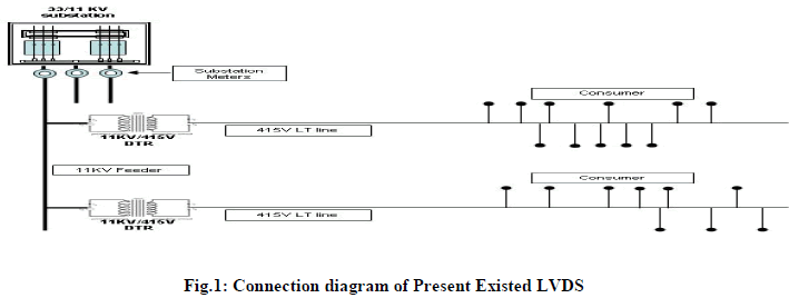 |
| Fig.1 depicts a 100kVA rating Mother DTR converts 11kV into 415V and is supplied to the consumer loads near substation.. A 100kVA DTR is supplying load to a particular area. In present system from Mother DTR to the loads, Low Tension lines are used by using the poles. |
DRAWBACKS OF LVDS |
| The drawbacks of low voltage distribution are as follows: (i) High Rating Distribution Transformers are required to supply the Power to the consumers. (ii)As low Voltages are transmitting to large distances, the voltage profile at the load ends is decreasing. (iii) More resistive loss is present because of low voltage profile. (iv) Agricultural Motor burnouts are more because the motor is tending to work under low voltage, dragging more current and leading to burnout of the motor windings. (v)There is a chance of theft of power at Agricultural areas by unauthorized connections.(vi) Improper load management results in overloading of conductors and transformers [5].(vii) Monitoring of unauthorized hooking or tapping the bare conductors is of LT lines is more difficult. [6] |
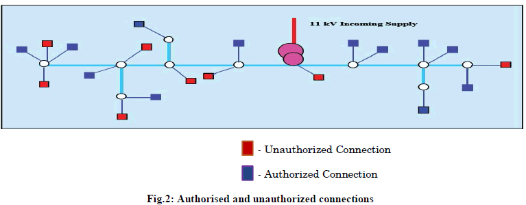 |
| Fig.2. shows that Blue loads are the authorized loads and the Red loads are unauthorized loads that mean that the unauthorized loads leading to the theft of the power. Only 12 consumers are authorized, but 8 more unauthorized connections are making all the consumers to suffer with low voltages. |
HIGH VOLTAGE DISTRIBUTION SYSTEMS |
| As Low Voltage Distribution System has many disadvantages, the High Voltage Distribution System (HVDS) is proposed. Three phase HVDS maintains better voltage profile to agricultural loads [7] .In HVDS instead of using Low Tension lines which transfer low voltages, High Tension lines are used in such a way that 11kV voltage is transferred near to the load centres |
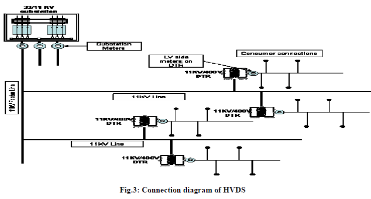 |
| Fig.3. shows the connection diagram of proposed HVDS system. 100kVA Mother Transformers are replaced with the small kVA rating DTR’s at the load centres and each DTR supply load only for 2 to 3 consumers according to the rating. |
ADVANTAGES OF HVDS OVER LVDS |
| The advantages of HVDS are (i) Low rating kVA Distribution Transformers are enough to supply loads. (ii)Voltage profiles at the loads will be improved, as the DTR’s are near to the load centres. (iii)As High Voltage is transferred near to the loads, the power loss will be less. (iv)Agricultural Motor burnouts will be eliminated because of good Voltage profiles. (v) Theft losses will be avoided completely because there is no scope of theft from 11kV line and for transmission of 415V, AB cable i.e., Aerial Bunch Cables are used.(vi) Reliability of the system can be increased. [8]. |
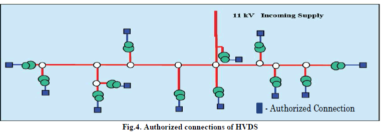 Fig.4. represents the authorised connections at various loads at various low KVA rating transformers. Fig.4. represents the authorised connections at various loads at various low KVA rating transformers. |
CASE STUDY |
LVDS Analysis: |
| Case study of Gundraju Kuppam SSII Feeder is presented in this paper. Gundraju Kuppam is the village which is 10km far away from Puttur and the substation has 11 feeders. It is supplying load for 22 Agricultural Consumers in which, the 11kV is stepped down to 415V by using 100kVA Distribution Transformer. The pole to pole distance is 40m. |
 |
 |
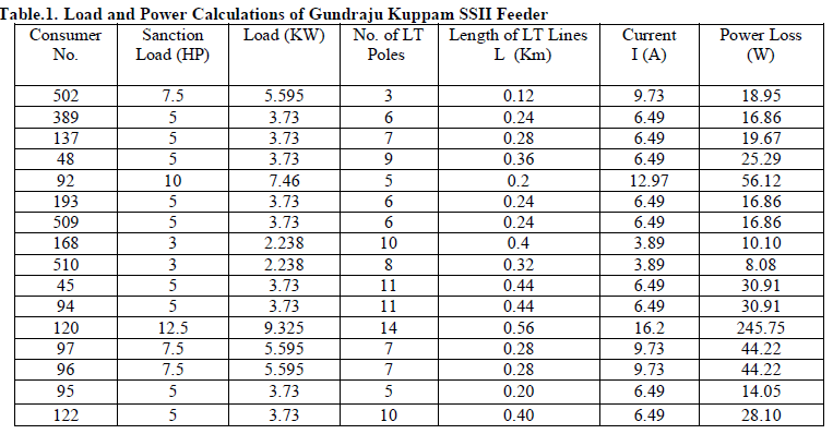
| Table.1 represents Load and Power Calculations of Gundraju Kuppam SSII Feeder based on sanction load, number of LT poles and length of transmission lines. |
| In the above table the sanction load is in HP and is converted into kW by using the formula 1HP = 0.746 kW. |
| Length of the LT line in Km = No. of Poles * Distance between the poles |
| Current per phase = (power) / (√3 * VL * cosÃâ¡Ã¿) |
| Power Loss = 3* I2* R* L |
| Where, R = Resistance of the Conductor = 0.556 Ω/ Km |
| Pole to Pole Distance = 40m = 0.040 Km |
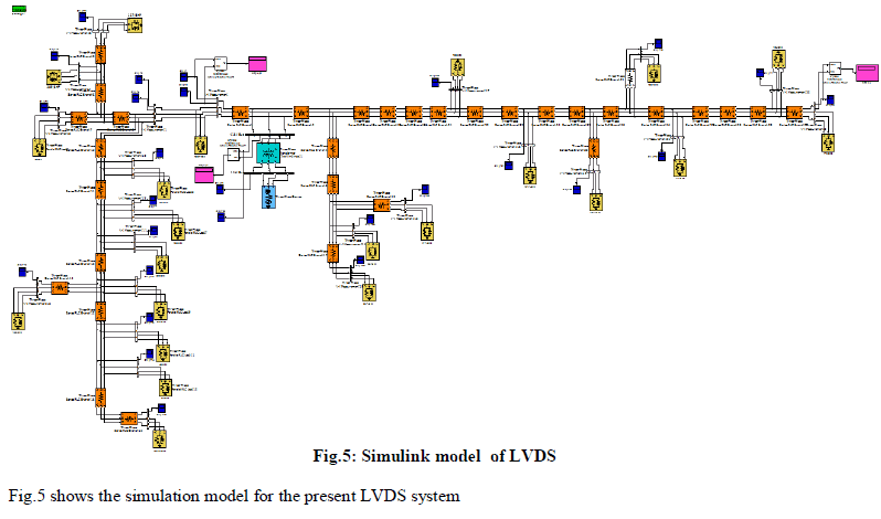
| The LVDS model is constructed as a Simulation model in MATLAB software and the results are simulated. The following are the Simulation model and Results of LVDS. |
SIMULATION DIAGRAM FOR LVDS |
 |
Loss calculation at various levels: |
(a) Line Loss Calculations [10]: |
| Total Power Loss = 1190.51 W |
| For Agricultural Loads, the Power is supplied for 7 Hours per day |
| Power Loss per Annum= (Power loss)* (No. of hours per day)* (No. of days per Annum)/1000=3041.75Units |
(b)Theft Losses: |
| 12% of Total load is lost due to theft |
| Total Theft Losses = 12% of Total Load=12.40KW |
| Total Theft Loss per Annum=31682 Units |
(c)Total Losses: |
| Net Losses = Total Power Loss per Annum + Total Theft Loss per Annum= 34723.75 Units |
HVDS Analysis: |
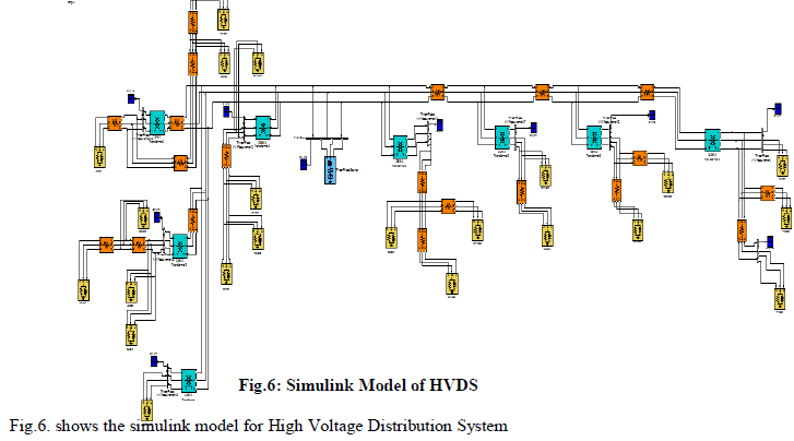
| In HVDS, the 100kVA Transformer is replaced by 25kVA and 16kVA Distribution Transformers to supply some appropriate loads. Up to the Distribution Transformers 11kV is supplied and at the Load end the small rating DTR’s converts 11kV into 415V and supplies the load. From DTR’s to the Load, Aerial Bunch (AB) cables are used. AB cables are insulated cable which helps in avoiding theft losses. |
 |
SIMULATION DIAGRAM FOR HVDS: |
 |
HVDS loss calculation: |
| Total Power Loss per Annum due to HVDS=(LVDS Power Loss)*(secondary voltage/primary voltage)2=4.33 Units |
| Net Reduction in Losses = Total LVDS Losses – Total HVDS Losses = 34719.42 Units |
Annual Savings: |
| Annual Savings = 7.35 * Reduction in Losses = Rs. 2, 55,187.74/- |
Pay Back Period Calculations: |
| Initial Investment cost of Transformers = 5, 24,000/- |
| Capital Layout = Total Transformer Cost + (Labour Cost & Miscellaneous cost) = Rs. 6, 44,000/- |
| Annual Savings = 7.35 * Reduction in Losses = Rs. 2, 55,187.74/- |
| Payback period = 2 years 6 months |
RESULTS AND DISCUSSIONS |
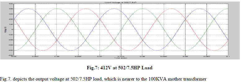
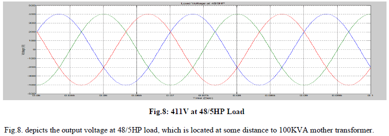
| In the above Simulation Model the loads are taken as RL loads and the load consumption power is from the table.1. The Transformer used is 100kVA Transformer which steps down 11kV Voltage to 415V. Initially, to give 11kV as input to the primary winding of the 100kVA Transformer a 3-phase Generator is used, which injects 11kV voltage to the 11kV bus. Three Phase VI Measurement blocks are used to measure the voltages and currents of the Lines. Scope is used to view the graphical results of the simulation model. The results for the Simulink model at different load points are as follows. |
 |
 |
 |
| Fig.9. depicts the output voltage at 120/12.5HP load, which is located far away at some distance to 100KVA mother transformer. |
 |
| Fig.10. depicts the output voltage at 172/5HP load, which is located far away to 100KVA mother transformer. |
| In the above results the extreme end loads are taken, to differentiate the Voltage profiles. It is clearly observed that the loads that are near to the Mother DTR is benefited with good Voltage profile while, the loads which are far away from Mother DTR, the voltage profiles are getting reduced and becoming worse [9]. At load number 172 the consumer is getting only 385V which is insufficient to drive the Motor, so that the motor takes more current and the windings of the motor leads to burnouts. |
| Present LVDS is replaced by HVDS. Simulink model is explained. A 100kVA Mother Transformer is replaced with small rating 25 & 16kVA Distribution Losses for the same loads. The simulation results are displayed. Input voltage remains same. There are some changes in output voltage at load side. |
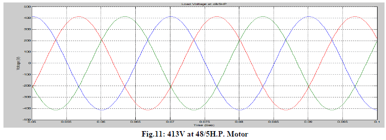 |
| Fig.11. depicts the output voltage at 48/5HP motor. |
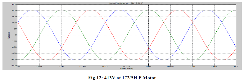 |
| Fig.12. depicts the voltage at 172/5H.P. Motor. |
| In HVDS, Voltage profile at all loads are constant i.e., 413V and hence there is a lot of improvement in voltage profiles & reduced power loss. As 11kV is extended up to load ends & AB cables are used for transmission, from DTR to loads, theft losses are avoided & voltage profiles are maintained. |
CONCLUSIONS |
| Finally it is concluded that, with the adoption of High Voltage for Distribution System i.e. HVDS, both the technical as well as non-technical losses are reduced. Firstly as in HVDS, the registered customers will feel ownership and take responsibility and not allow others to meddle with the LT Network and can even prevent unauthorized loads by the consumers themselves, since the distribution transformer may fail if loaded beyond its capacity, which reduces the failure rate because of no over loading and no meddling of LT Lines and failure will affect only two or three customers instead of 25 to 30 customers in original system. Effective implementation of HVDS scheme has reduced the failure of transformers, burning of agricultural pump sets and curtailment of demand through retrofitting of energyefficient pumps. This in-turn, reduces the wastage of energy and optimization of power intake, there by promoting the environmental concerns and because of reduced consumption, the farmer gets benefited by the reduction in his monthly expenditure on electricity. It is concluded that the use of distribution transformer of small rating for two or three consumers has reduced the outages, transformer and power losses due to low current and pilferage to a great extent. Also, the accountability of the farmer has increased resulting in moral ownership of the transformer dedicated to single pump. HVDS is more advantageous than LVDS as it has Improved Voltage profile and Reduced Power Loss. Even though there is a drawback of high initial investment, the payback period is very less. So, converting LVDS lines to HVDS lines will become more beneficiary to our future generation with less Distribution loss and less Agricultural Motor burnouts. |
References |
|