ISSN ONLINE(2278-8875) PRINT (2320-3765)
ISSN ONLINE(2278-8875) PRINT (2320-3765)
| Sathishkumar N, Finney Daniel Shadrach S, Balamurali S Assistant Professor, Dept. of ECE, KPR Institute of Engineering & Technology, Coimbatore, India |
| Related article at Pubmed, Scholar Google |
Visit for more related articles at International Journal of Advanced Research in Electrical, Electronics and Instrumentation Engineering
In this paper, the methodology to reduce the mutual coupling using inductive loading is proposed which is achieved by the use of shorting pins placed in between the patch and the ground plane. The performance improvement can be seen in the result, and the side lobe levels are reduced using the Gaussian and Rayleigh functions, according to which the antenna weights are designed in the proposed 1x7 array.
Keywords |
| Radiation Pattern,Mutual coupling, Side lobe level, Inductive loading |
INTRODUCTION |
| Nowadays microstrip structures are most sought because of their compact nature, low fabrication cost, and light weight. The microstrip patch antennas can be easily integrated with MIC’s. Mutual coupling exists between individual elements in the PAA due to radiation in the horizontal plane. This degrades the performance of the antenna and the main beam may be steered away from the desired direction in some cases. Many methods have been proposed and lot of research is done to reduce mutual coupling. |
| Attempts have been made to reduce the mutual coupling by inserting various types of EBG’s between antenna elements of phased arrays. To reduce the radiation along the horizontal plane, patch antennas with an array of pins interconnecting the patch and the ground were investigated. The side lobes which scatter the power in undesired directions pose a problem in beam steering. So we propose to find the antenna weights using Gaussian or Rayleigh functions, and a drastic improvement is found when compared with the case where no weights are used. For reduction of side lobes phase tapering, schelkunoff polynomial method, geometric linear programming are proposed in [2]. |
| This paper proposes an inductive loaded patch antenna as an element of a probe-fed phased array antenna (PAA) in order to improve its radiation characteristics by the suppression of mutual coupling. The radiation characteristics of theproposed antenna are simulated using ADS. The reduction of mutual coupling using shorting pins is investigated in [1], and in addition to that work, a method for weighting the antenna elements is proposed in this paper. |
 |
IMPLEMNTATION AND RADIATION CHARACTERISTICS |
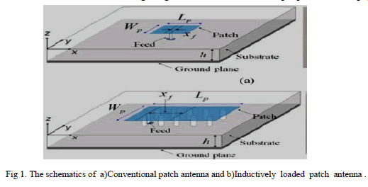
| All the antennas are fabricated on Rogers 4003 with a thickness of 3.2 mm, dielectric constant of 10.2, and loss tangent of 0.0035. Two types of patch antennas with the resonant frequency of 5 GHz have been designed to use antenna elements of array antennas. Fig. 1(a) and (b) shows schematics of the conventional patch antenna and inductively loaded patch antenna. The dimensions ofthe grounded substrates of the two fabricated patch antennasareboth60x 60mm2 (λ0 x λ0). The 50 Ω probe fed point (ïÿýïÿýïÿýïÿý ) is the offset from the centre of the patch in the x-axis. The patch size (LpxWp) of the conventional patch antenna is 7.6 x 6.1mm2andïÿýïÿýïÿýïÿý is 1.15 mm. The patch size of the inductively loaded patch antenna is 27.5 x 11.3mm2 with a pin radius of 1.0 mm2 and ïÿýïÿýïÿýïÿý is 12.05mm2. |
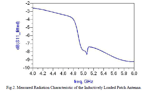 |
| The above figure shows the radiation characteristic of the single inductively loaded patch antenna. The measured return loss is shown in figure 2. Since the effective dielectric constant of the substrate underneath the patch of the inductively loaded patch antenna is close to 1, its radiation along the horizontal plane is greatly suppressed compared to that of the conventional patch antenna, and the patch area of the inductively loaded patch antenna is much larger than that of the conventional patch antenna. Thus the broadside gain of the inductive loaded patch antenna is higher than that of the conventional patch antenna. |
PERFORMANCE OF A LINEAR PHASED ARRAY ANTENNA COMPOSED OF INDUCTIVELY LOADED PATCH ANTENNAS |
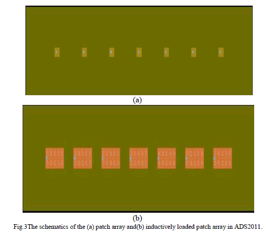
| The figure 3 shows the design of array antennas. Figures 3(a) and 3(b) show the schematics of the 1x7 conventional patch array and inductively loaded patch antenna respectively. The dimensions of the grounded substrates of the two fabricated linear PAA’S are 348x60mm2 (5.8λ0 x 1.0λ0). On comparison of the mutual coupling between the elements in the arrays in 3(a) and 3(b), the mutual coupling is reduced in the second case because the inductively loaded patches are used. |
 |
 |
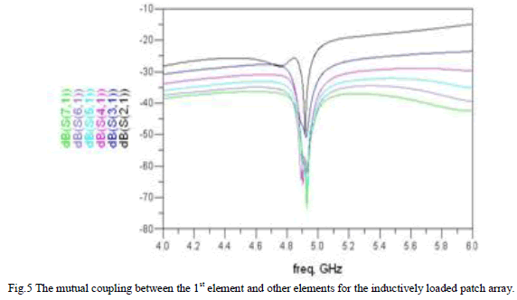 |
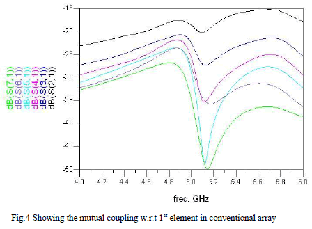
| The figure 5 shows the mutual coupling between the 1st element and the remaining elements. It can be seen that the mutual coupling is a function of the distance naturally. Comparing figures 4 and 5 an improvement of 5.5 dB can be seen in the latter case. This is due to the negative feedback mechanism due to the placement of shorting pins. But as a consequence of placing these shorting pins, the gain comes down. However this can be compensated by increasing the voltage/ increasing the number of elements. |
| The reduction in the gain of the inductively loaded patch array compared to the conventional array is the negative feedback through which the inductive currents cancel out [9]. |
| Figures 4 depicts the mutual coupling w.r.t the first element in conventional patch array and inductively loaded patch array respectively, for the 1x7 array. And also we can infer from the graph that the mutual coupling is a function of the distance between the elements, since it has been reduced monotonically as we progressed from 2nd element to 6th element. |
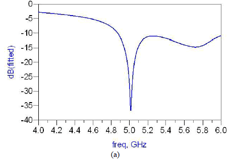
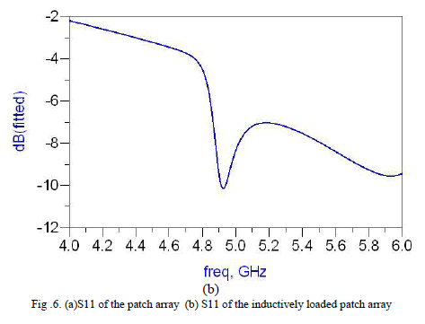
| The figures 6(a) and 6(b) show the S11 of the patch arrays i.e the conventional and inductively loaded arrays respectively. |
SIMULATION AND RESULTS |
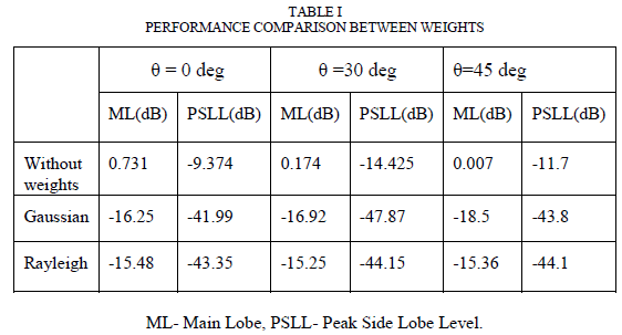
| The side lobe levels are a major problem of concern while aligning the nulls in the unwanted direction. Geometric Linear Programming and DolphChebyshev method for Sidelobe Level reduction are proposed in [4]. To avoid complex programming the weighting functions are chosen to be Gaussian and Rayleigh Distributions. And the results are compared. The table below shows the comparison between the two functions. |
 |
| The Gaussian Function with variance=1 and mean =0 given by |
| F(x)=(1/2π)0.5 . e (-(x^2)/2) |
| for x=0,1,2,3,….. |
| The Rayleigh function is given by |
| F(x)=xe(-(x^2)/2) |
| for x=1,2,3,… |
| These Gaussian and Rayleigh weights are applied to a symmetric array. For the shown 1x7 array. We can observe that the Gaussian function works better than the Rayleigh function. |
 |
 |
CONCLUSION |
| It is clear that gain of the inductively loaded patch antenna is reduced compared to the conventional case, because it is a closed loop feedback system , so performance improves and gain decreases..Hence to avoid complex programming to find out the weights of the antenna, the random distribution functions are used to combat this problem. And this antenna can be used for 5GHz unlicensed band applications. |
References |
|