ISSN ONLINE(2319-8753)PRINT(2347-6710)

All submissions of the EM system will be redirected to Online Manuscript Submission System. Authors are requested to submit articles directly to Online Manuscript Submission System of respective journal.

Reduction of Ripple in the Bidirectional DC-DC Converter with the Coupled Inductor

K.C.Ramya 1, V.Jegathesan 2
  1. Research Scholar, Department of Electrical and Electronics Engineering, Karunya University, Coimbatore, India1
  2. Associate Professor, Department of Electrical and Electronics Engineering, Karunya University, Coimbatore, India2
Related article at Pubmed, Scholar Google

Visit for more related articles at International Journal of Innovative Research in Science, Engineering and Technology

Abstract

This work deals with reduction of ripple in the bidirectional DC-DC converter. This Converter has the ability to transfer the energy in both the directions. This converter is designed, modeled and simulated using MATLAB SIMULINK and the results are presented. The Pi-filter is proposed at the output to reduce the peak to peak ripple. The simulation results with R-load and DC-Motor load are presented.

Keywords

Bidirectional DC-DC converter, Coupled Inductor, Filter.

INTRODUCTION

Bidirectional DC–DC converters (BDC) are used to transfer the power between two DC sources in either direction. These converters are widely used in applications, such as hybrid electric vehicle energy systems [1]–[4], uninterrupted power supplies [5], [6], fuel-cell hybrid power systems [7]–[10], photovoltaic hybrid power systems [11], [12], and battery chargers [13]–[15]. Many bidirectional DC-DC converters have been researched. The bidirectional DC-DC flyback converters are more attractive due to simple structure and easy control [2], [16], [17]. However, these converters suffer from high voltage stresses on the power devices due to the leakage inductor energy of the transformer. In order to recycle the leakage inductor energy and to minimize the voltage stress on the power devices, some literature present the energy regeneration techniques to clamp the voltage stress on the power devices and to recycle the leakage inductor energy [18], [19]. Some literatures research the isolated bidirectional DC-DC converters, which include the half-bridge [8], [9], [20], [21] and full-bridge types [13], [22]. These converters can provide high step-up and stepdown voltage gain by adjusting the turns ratio of the transformer.
image
image
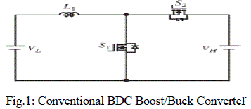
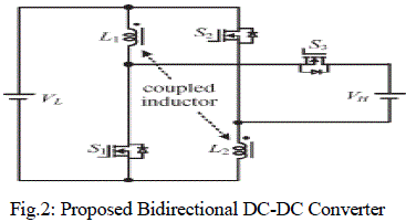
For non-isolated applications, the non-isolated bidirectional DC-DC converters, which include the conventional boost/buck [1], [5], [12], [14], multilevel [4], three-level [10], sepic/zeta[23], switched capacitor [24], and coupled inductor types [25], are presented. The multilevel type is a magnetic less converter, but 12 switches are used in this converter. If higher step-up and step-down voltage gains are required, more switches are needed. This control circuit becomes more complicated. In the three-level type, the voltage stress across the switches on the three-level type is only half of the conventional type. However, the step-up and step-down voltage gains are low. Since the sepic/zeta type is a combination of two power stages, the conversion efficiency will be decreased. The switched capacitor and coupled inductor types can provide high step-up and step-down voltage gains. However, their circuit configurations are complicated. Fig.1 shows the conventional bidirectional DC-DC boost/buck converter which is simple structure and easy control. However, the step-up and step-down voltage gains are low. A modified DC-DC boost converter is presented [26]. The voltage gain of this converter is higher than the conventional DC-DC boost converter. Based on this converter, a novel bidirectional DC-DC converter is proposed [27], as shown in Fig. 2. The proposed converter employs a coupled inductor with same winding turns in the primary and secondary sides. Compared to the proposed converter and the conventional bidirectional boost/buck converter, the proposed converter has the following advantages:1) Higher step-up and step-down voltage gains and 2) lower average value of the switch current under same electric specifications. The following sections will describe the operating principles and steadystate analysis for the step-up and step-down modes. In order to analyze the steady-state characteristics of the proposed converter, some conditions are assumed: The on-state resistance RDS(ON) of the switches and the equivalent series resistances of the coupled inductor and capacitors are ignored; the capacitor is sufficiently large; and the voltages across the capacitor can be treated as constant.
The above literature does not deal with ripple reduction using Pi-filter. This work proposes Pi-filter for ripple reduction.

II. STEP-UP MODE

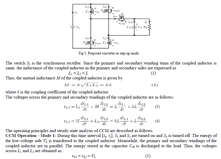
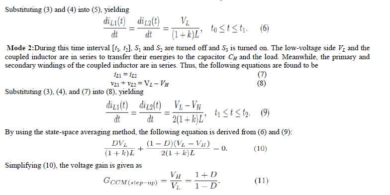
The proposed converter in step-up mode is shown in Fig.3.The pulse width modulation (PWM) technique is used to control the switches S1 and S2 simultaneously.
image
image

III. SIMULATION RESULTS

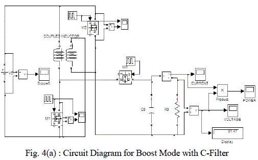
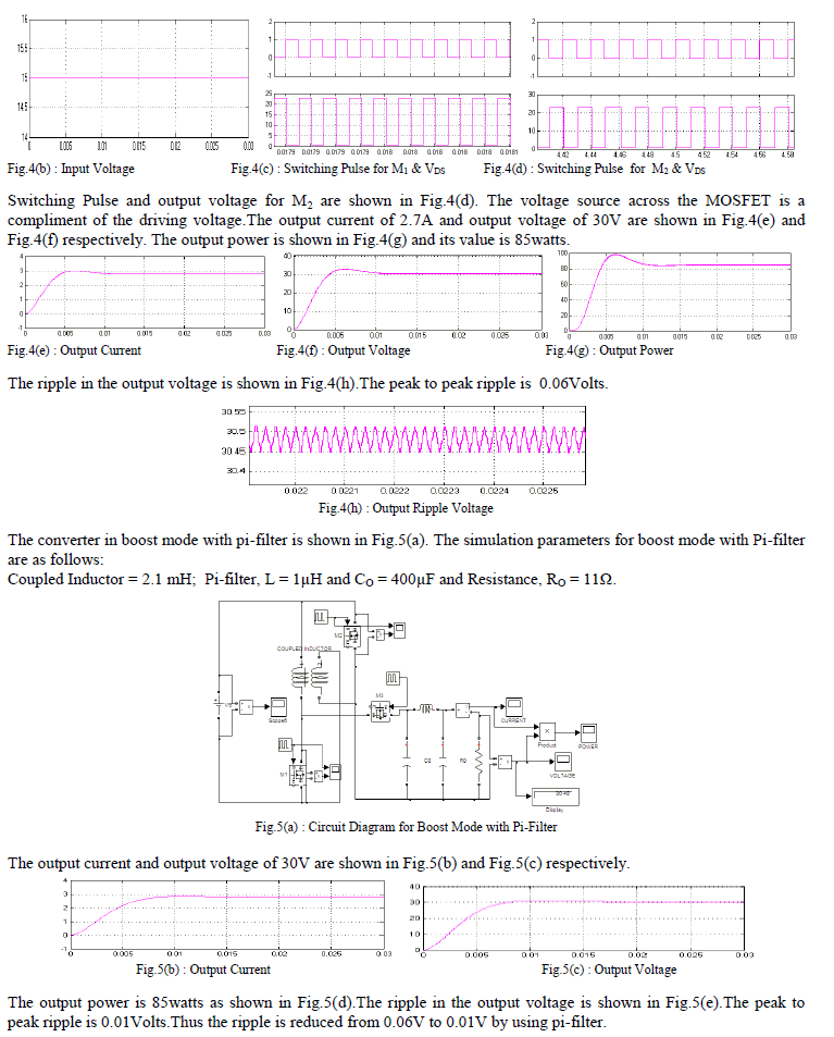
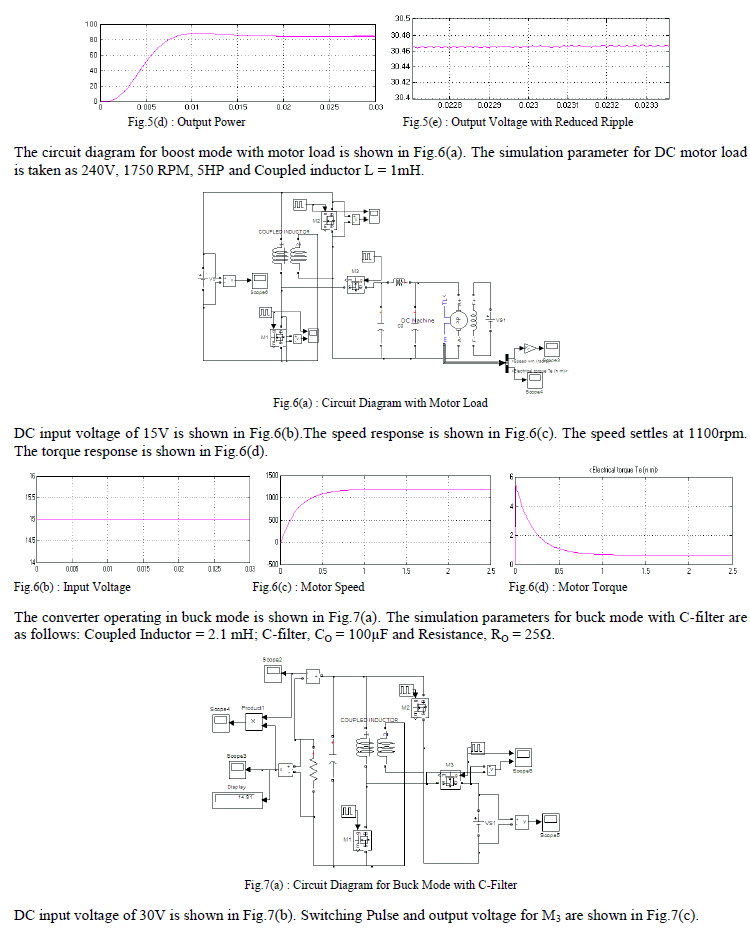
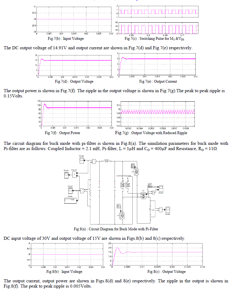
The circuit diagram for boost mode is shown in Fig.4(a).The power output is measured by multiplying the output voltage and the output current. Load voltage and load current are measured using voltage and current blocks respectively.The following are the assumptions made in simulation studies.  Internal resistance of the source is neglected.  Resistance of the coupled inductor is neglected.  ESR of the capacitor is neglected. The simulation parameters for boost mode with C-filter are as follows: Coupled Inductor = 1 mH ; C-filter, CO = 400μF and Resistance, RO = 11Ω.
image
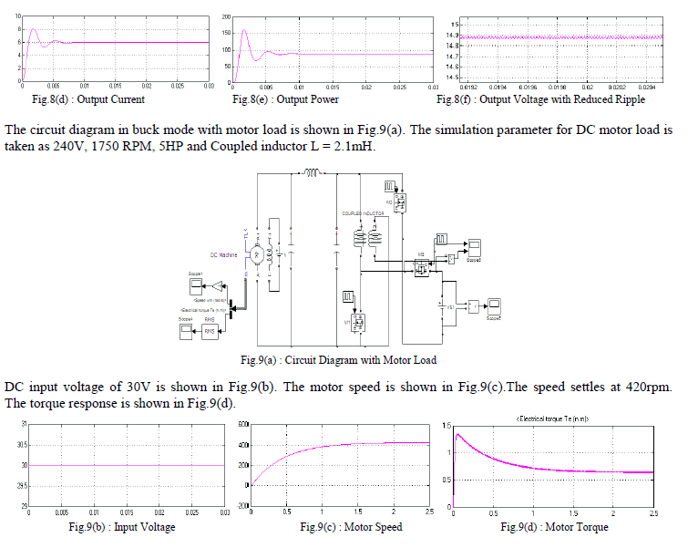
DC input voltage of 15V is shown in Fig.4(b). The switching voltage and the voltage across the MOSFET are shown in Fig.4(c).
iamge
image
image
image

IV. CONCLUSION

Bidirectional DC-DC converter operating in boost mode and buck mode is simulated successfully with R-load and DC motor load. The ripple in the output voltage is reduced from 0.06Volts to 0.01Volts by using Pi-filter. Therefore the performance of DC motor is improved due to the reduced ripple. The scope of this work is to design and simulate the DC-DC converter using MATLAB. The hardware will be implemented in future. The drawback of this converter is that it can be used only for low power levels.

References

  1. M. B. Camara, H. Gualous, F. Gustin, A. Berthon, and B. Dakyo, ―DC/DC converter design for supercapacitor and battery power management in hybrid vehicle applications—Polynomial control strategy,‖ IEEE Trans. Ind. Electron., vol. 57, no. 2, pp. 587–597, Feb. 2010.
  2. T. Bhattacharya, V. S. Giri, K. Mathew, and L. Umanand, ―Multiphase bidirectional flyback converter topology for hybrid electric vehicles,‖ IEEE Trans. Ind. Electron., vol. 56, no. 1, pp. 78–84, Jan. 2009.
  3. Z. Amjadi and S. S. Williamson, ―A novel control technique for a switched-capacitor-converter-based hybrid electric vehicle energy storage system,‖ IEEE Trans. Ind. Electron., vol. 57, no. 3, pp. 926–934,Mar. 2010.
  4. F. Z. Peng, F. Zhang, and Z. Qian, ―A magnetic-less dc–dc converter for dual-voltage automotive systems,‖ IEEE Trans. Ind. Appl., vol. 39, no. 2, pp. 511–518, Mar./Apr. 2003.
  5. A. Nasiri, Z. Nie, S. B. Bekiarov, and A. Emadi, ―An on-line UPS system with power factor correction and electric isolation using BIFRED converter,‖ IEEE Trans. Ind. Electron., vol. 55, no. 2, pp. 722–730, Feb. 2008.
  6. L. Schuch, C. Rech, H. L. Hey, H. A. Grundling, H. Pinheiro, and J. R. Pinheiro, ―Analysis and design of a new high -efficiency bidirectional integrated ZVT PWM converter for DC-bus and battery-bank interface,‖IEEE Trans. Ind. Appl., vol. 42, no. 5, pp. 1321–1332, Sep./Oct. 2006.
  7. X. Zhu, X. Li, G. Shen, and D. Xu, ―Design of the dynamic power compensation for PEMFC distribu ted power system,‖ IEEE Trans. Ind. Electron., vol. 57, no. 6, pp. 1935–1944, Jun. 2010.
  8. G. Ma, W. Qu, G. Yu, Y. Liu, N. Liang, and W. Li, ―A zero-voltageswitching bidirectional dc–dc converter with state analysis and softswitchingoriented design consideration,‖ IEEE Trans. Ind. Electron.,vol. 56, no. 6, pp. 2174–2184, Jun. 2009.
  9. F. Z. Peng, H. Li, G. J. Su, and J. S. Lawler, ―A new ZVS bidirectional dc–dc converter for fuel cell and battery application,‖ IEEE Trans. PowerElectron., vol. 19, no. 1, pp. 54–65, Jan. 2004.
  10. K. Jin, M. Yang, X. Ruan, and M. Xu, ―Three-level bidirectional converter for fuel-cell/battery hybrid power system,‖ IEEE Trans. Ind. Electron., vol. 57, no. 6, pp. 1976–1986, Jun. 2010.
  11. R. Gules, J. D. P. Pacheco, H. L. Hey, and J. Imhoff, ―A maximum power point tracking system with parallel connection for PV stand-alone applications,‖ IEEE Trans. Ind. Electron., vol. 55, no. 7, pp. 2674–2683,Jul. 2008.
  12. Z. Liao and X. Ruan, ―A novel power management control strategy for stand-alone photovoltaic power system,‖ in Proc. IEEE IPEMC, 2009,pp. 445–449.
  13. S. Inoue and H. Akagi, ―A bidirectional dc–dc converter for an energy storage system with galvanic isolation,‖ IEEE Trans. Power Electron.,vol. 22, no. 6, pp. 2299–2306, Nov. 2007.
  14. L. R. Chen, N. Y. Chu, C. S. Wang, and R. H. Liang, ―Design of a reflexbasedbidirectional converter with the energy recovery function,‖ IEEE Trans. Ind. Electron., vol. 55, no. 8, pp. 3022–3029, Aug. 2008.
  15. S. Y. Lee, G. Pfaelzer, and J. D.Wyk, ―Comparison of different designs of a 42-V/14-V dc/dc converter regarding losses and thermal aspects,‖ IEEE Trans. Ind. Appl., vol. 43, no. 2, pp. 520–530, Mar./Apr. 2007.
  16. K. Venkatesan, ―Current mode controlled bidirectional flyback converter,‖ in Proc. IEEE Power Electron. Spec. Conf., 1989, pp. 835–842.
  17. T. Qian and B. Lehman, ―Coupled input-series and output-parallel dual interleaved flyback converter for high input voltage application,‖ IEEE Trans. Power Electron., vol. 23, no. 1, pp. 88–95, Jan. 2008.
  18. G. Chen, Y. S. Lee, S. Y. R. Hui, D. Xu, and Y. Wang, ―Actively clamped bidirectional flyback converter,‖ IEEE Trans. Ind. Electron., vol. 47, no. 4, pp. 770–779, Aug. 2000.
  19. F. Zhang and Y. Yan, ―Novel forward-flyback hybrid bidirectional dc–dc converter,‖ IEEE Trans. Ind. Electron., vol. 56, no. 5, pp. 1578– 1584,May 2009.
  20. H. Li, F. Z. Peng, and J. S. Lawler, ―A natural ZVS medium-power bidirectional dc–dc converter with minimum number of devices,‖ IEEE Trans. Ind. Appl., vol. 39, no. 2, pp. 525–535, Mar. 2003.
  21. B. R. Lin, C. L. Huang, and Y. E. Lee, ―Asymmetrical pulse-width modulation bidirectional dc–dc converter,‖ IET Power Electron., vol. 1, no. 3, pp. 336–347, Sep. 2008.
  22. Y. Xie, J. Sun, and J. S. Freudenberg, ―Power flow characterization of a bidirectional galvanically isolated high-power dc/dc converter over a wide operating range,‖ IEEE Trans. Power Electron., vol. 25, no. 1, pp. 54–66, Jan. 2010.
  23. I. D. Kim, S. H. Paeng, J. W. Ahn, E. C. Nho, and J. S. Ko, ―New bidirectional ZVS PWM sepic/zeta dc–dc converter,‖ in Proc. IEEE ISIE, 2007, pp. 555–560.
  24. Y. S. Lee and Y. Y. Chiu, ―Zero-current-switching switched-capacitor bidirectional dc–dc converter,‖ Proc. Inst. Elect. Eng.—Elect. Power Appl., vol. 152, no. 6, pp. 1525–1530, Nov. 2005.
  25. R. J. Wai and R. Y. Duan, ―High-efficiency bidirectional converter for power sources with great voltage diversity,‖ IEEE Trans. Power Electron.,vol. 22, no. 5, pp.1986–1996, Sep. 2007.
  26. L. S. Yang, T. J. Liang, and J. F. Chen, ―Transformerless dc–dc converters with high step-up voltage gain,‖ IEEE Trans. Ind. Electron., vol. 56, no. 8,pp. 3144–3152, Aug. 2009.
  27. Lung-Sheng Yang and Tsorng-Juu Liang,‖Analysis and Implementation of novel bidirectional dc-dc converter,‖ IEEE Trans.Ind.Electron, vol.59, no.1, Jan.2012.