ISSN ONLINE(2278-8875) PRINT (2320-3765)
ISSN ONLINE(2278-8875) PRINT (2320-3765)
M. V. G. Vara Prasad1, R. S. Ravi Sankar2, Dr. K. Alice Mary3
|
| Related article at Pubmed, Scholar Google |
Visit for more related articles at International Journal of Advanced Research in Electrical, Electronics and Instrumentation Engineering
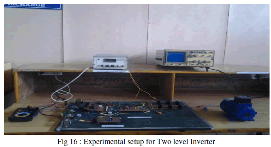
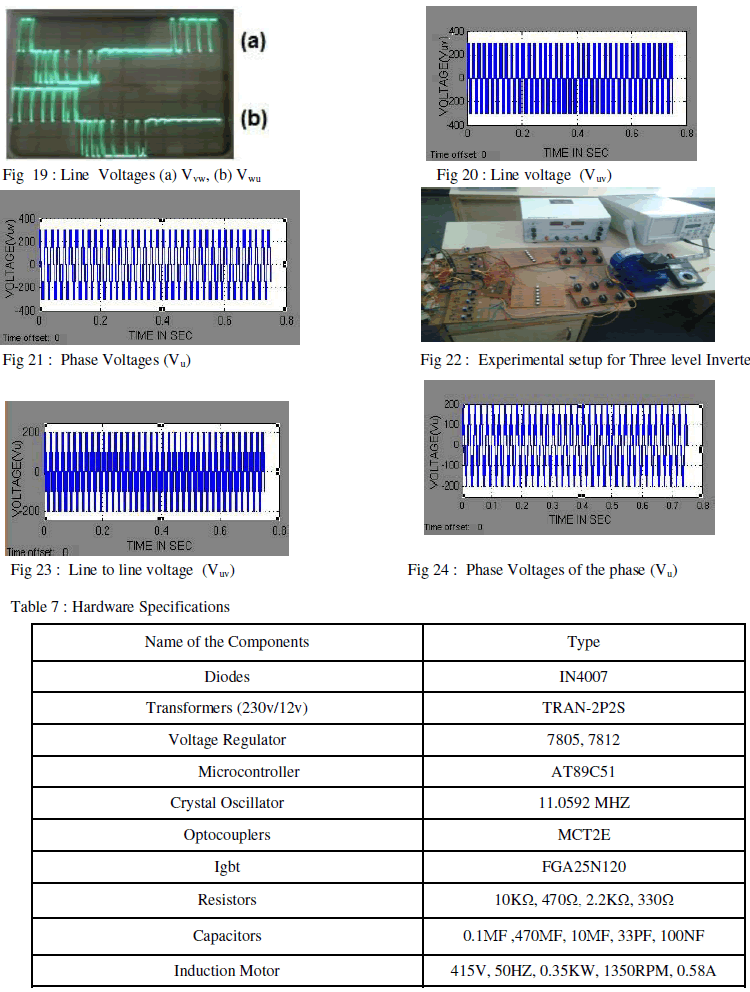
This paper proposes a approach in direct torque control (DTC) i.e. the applied voltage is a function of rotor speed and describes a new switching state algorithm which gives an optimum flux & torque ripple at steady state condition & fast dynamic torque response [1]. This approach is applied to two-level and three-level inverters. Simulation results for proposed two level DTC and proposed three level DTC techniques for various speed conditions (very low, low, rated, and high speeds) are compared. The proposed two level and three level inverters fed three phase asynchronous machine using Micro Controller in open loop is implemented through hardware realization.
Keywords |
| Direct Torque Control, Multilevel Inverter, Induction Motor, Switching State Algorithm |
INTRODUCTION |
| The difference between conventional Direct Torque Control (conventional DTC) and proposed Direct Torque Control (proposed DTC) i.e. a model of three level Neutral Point Clamped (NPC) inverters (cascaded two level inverters). The control strategy optimizes the current ripple (Flux and Torque ripple) in steady state condition and fast dynamic torque response in transient state. The proposed model type inverters are used because they are provided high safety voltages with less harmonic components compare to two level structures [7]. As the number of levels is increasing the implementation of space vector modulation technique (SVPWM) becomes difficult, because the design of flux and torque controller for three level inverter is difficult [3]. |
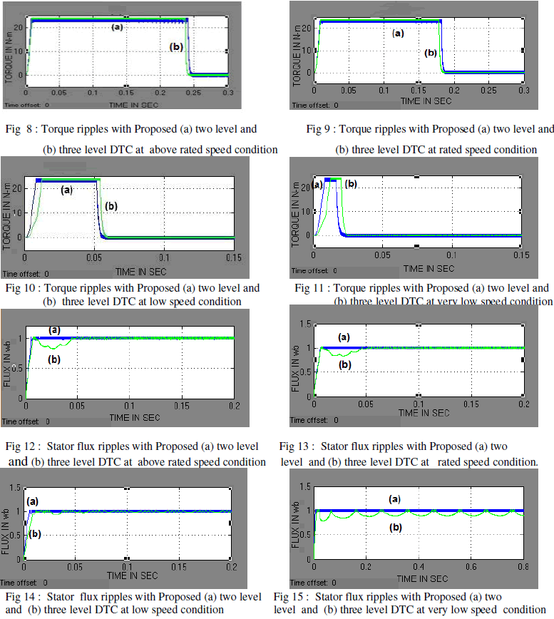
| So a proposed switching state algorithm is used to trigger the switching devices. And simulation results are observed for both proposed two and three level DTC techniques for various speed conditions (very low <25% of rated speed, low 25% to 50% of rated speed, rated, and high >50 % of rated speeds). And it is observed those torque and stator flux ripples are lesser for proposed three level DTC. With available results of both proposed two and three level DTC laid a path for open loop hardware for both two and three level inverter using Micro Controller is enhanced |
MODELING OF INDUCTION MOTOR |
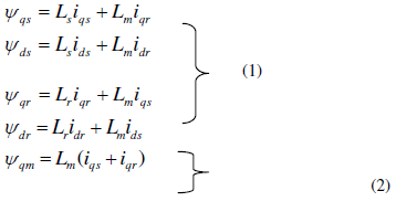
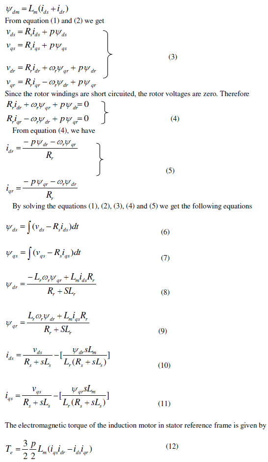
| The modeling of Induction Motor in stationary reference frame using Stanley model is as follows [13], |
 |
 |
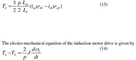 |
| This model is used when stator variables are required to be actual i.e. the same as in the actual machine stator and rotor variables can be fictitious. This reduces the number of competitions and thus lends themselves to real time control applications in high performance variable speed drives requiring the computation of stator currents, flux linkages and electromagnetic torque. |
CONTROL METHOD |
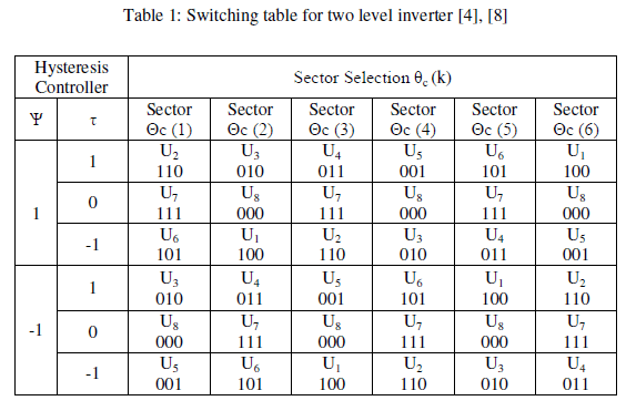
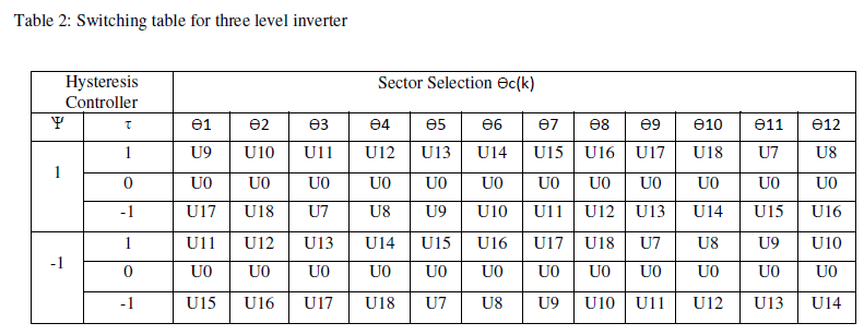
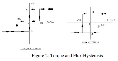
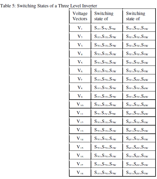
| Two stator currents ia and ib are sensed. stator voltage and currents as d-q vectors in the stationary reference frame are computed and the stator flux and electric torque are calculated and compared with their reference values using the hysteresis comparators as shown in figure 2 and then the output of this comparator are fed to the look up table of switching information to select an appropriate inverter voltage vector which is applied based on the position of the stator flux and the required changes in magnitude of stator flux and torque, thus the selected voltage vector will be applied to asynchrous motor. For two level inverter there are six equally spaced voltages having the same magnitude and zero voltage vectors as shown in table 1. And for three level inverter there are eighteen equally spaced voltages having the same magnitude and zero voltage vectors for certain speed operation of asynchronous drive is as shown in table 2 and optimum switching is shown in table 3. Hence each sector in two level inverter is of 600 and similarly for three level inverter it is 300 |
| The control method proposed is as shown below |
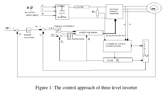 |
| In DTC torque and flux are controlled independently by selecting the optimum voltage space vector for entire switching period and the error signal is given to the hysteresis band, for small errors the motor torque may exceed the upper/lower torque limit [10]. The slip frequency can be controlled by introducing zero vectors. Switching frequency always varies according to the width of hysteresis band. Three level inverter is proposed in this paper as the harmonics are lesser compared to the two level inverter. |
 |
 |
| Where, |
| U0 - 000000000000, U1 - 110001101010, U2 - 111000101010, U3 - 011100101010, U4 - 001110101010, |
| U5 - 000111101010, U6 -100011101010, U7 - 110001110001, U8 - 110001111000, U9 - 111000111000, |
| U10 - 011100111000, U11 - 011100011100, U12 -011100001110, U13 - 001110001110, U14 - 000111001110, |
| U15 - 000111000111, U16 - 000111100011, U17 - 100011100011, U18 - 110001100011 |
 |
OPERATION OF INDUCTION MOTOR AT VARIOUS SPEEDS FOR THREE LEVEL INVERTER |
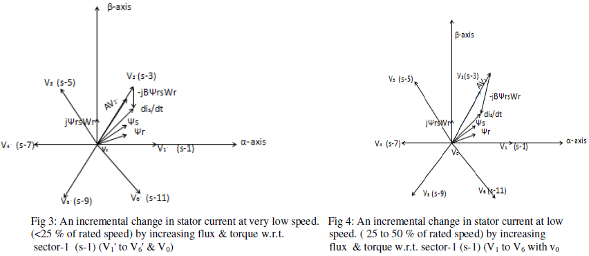
| The choice of voltage vector between V1' to V6' vectors and null vector V0 is selected for very low speed operation. The voltage vector is divided in 12 sectors in α-β plane as shown in figure 3. The selection of voltage vectors depends on the flux error, torque error and also sector number. For example, the selection of V1', V2'& V6' voltage vectors increases the stator flux magnitude for any position of Ãâðs in sector 1 similarly V3', V4'& V5' voltage vectors decreases the stator flux magnitude. Positive torque errors are compensated by selecting V2' and V3' voltage vectors in sector 1 and negative torque errors are compensated by selecting V5' and V6' in the same sector. |
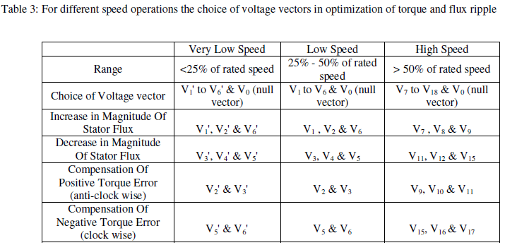 |
| The choice of voltage vector between V1 to V6 vectors and null vector V0 is selected for low speed operation. The voltage vector is divided in 12 sectors in α-β plane as shown in figure 5. The selection of voltage vectors depends on the flux error, torque error and also sector number. For example, the selection of V1, V2& V6 voltage vectors increases the stator flux magnitude for any position of Ãâðs in sector 1 similarly V3, V4& V5 voltage vectors decreases the stator flux magnitude. Positive torque errors are compensated by selecting V2 and V3 voltage vectors in sector 1 and negative torque errors are compensated by selecting V5 and V6 in the same sector. |
| The choice of voltage vector between V7 to V18 vectors and null vector V0 is selected for high speed operation. The voltage vector is divided in 12 sectors in α-β plane as shown in figure 5. The selection of voltage vectors depends on the flux error, torque error and also sector number. For example, the selection of V7, V8& V9 voltage vectors increases the stator flux magnitude for any position of Ãâðs in sector 1 similarly V11, V12 & V15 voltage vectors decreases the stator flux magnitude. Positive torque errors are compensated by selecting V9, V10 and V11 voltage vectors in sector 1 and negative torque errors are compensated by selecting V15, V16& V17 in the same sector. |
OPERATION OF VOLTAGE VECTORS TO OPTIMIZE TORQUE AND FLUX RIPPLE |
| As the flux and torque ripples are function of current ripple and in order to optimize the torque and flux ripples of 3-Φ asynchronous machine is based on reduction of torque ripple [10]. |
 |
 |
 |
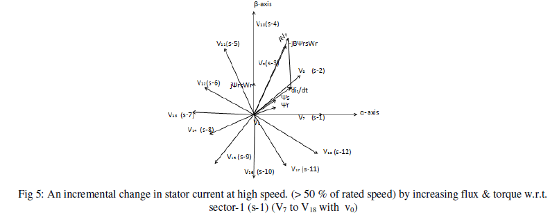 |
| From fig (3), (4)& (5) shows how the current ripple is varying for very low, low and high speeds and the incremental change in current ripple for various speeds. For suppose the stator flux vector is 1 and for very low speed the choose of voltage vector V2', the flux and torque values are increased then current ripple will decreased. For suppose the stator flux vector is 1 and for low speeds the choose of voltage vector V2, the flux and torque values are increased then current ripple will decreased. For supposed the stator flux vector is 1 and for high speeds the choose of voltage V9, the flux and torque values are increased then the current ripple will decreased. |
SIMULINK BLOCK |
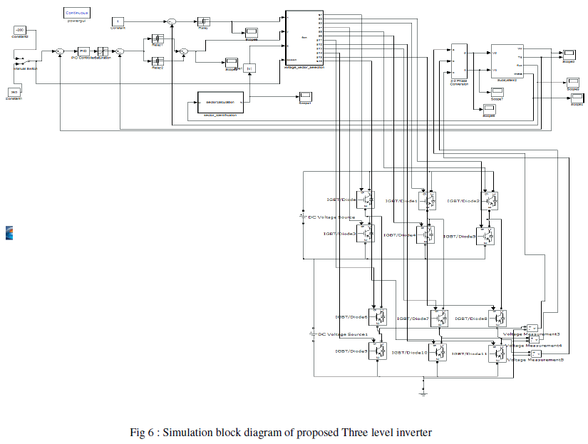 |
PROPOSED THREE LEVEL MULTI LEVEL INVERTER |
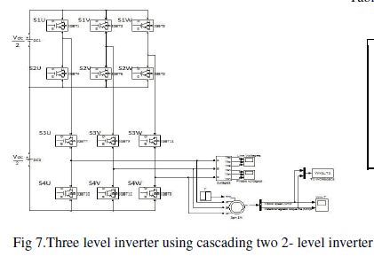
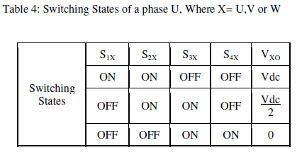
| The proposed three level inverter which is shown below is cascaded two level inverter configuration, this scheme does not experience the neutral point fluctuations, which even has less number of switching devices as compared to conventional one. The power supplies are required for proposed topology is less when compared to conventional one [9], [12]. |
| Advantages of multi level inverters are [6], [5]: |
| (i) High voltage |
| (ii)High power with less harmonics in output with optimum switching frequency. |
| (iii)The required voltage rating of the devices is lower and equal to half of the dc link voltage. |
 |
 |
 |
SIMULATION RESULTS |
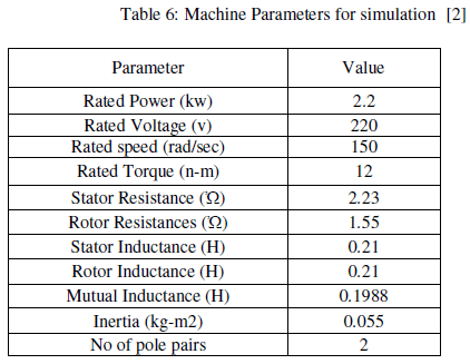
| The entire developed model is analyzed and simulation results are carried out for 3-Φ asynchronous machine for both two and three level inverters at different operating speeds and the results are compared for both two and three level inverters in SIMULINK/MATLAB. |
 |
 |
EXPERIMENTAL SETUP |
 |
 |
 |
CONCLUSION |
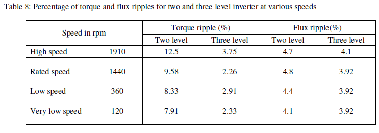
| In this paper, the torque and flux ripple minimization for proposed two level DTC and proposed three level DTC of 3-Ø Induction Motor drive, using an efficient switching algorithm is discussed and it is justified that torque and flux ripples are low for three level inverter. A hardware implementation of two and three level inverter in open loop using micro controller, and results of torque and flux errors for both two level and three level inverters for different speeds are calculated and observed that for wide range of speeds, torque and flux ripples are drastically reduced by using three level inverter. |
 |
References |
|