ISSN ONLINE(2278-8875) PRINT (2320-3765)
ISSN ONLINE(2278-8875) PRINT (2320-3765)
Sukes Maiti1, Saibal Pradhan2 and Susanta Sen3
|
| Related article at Pubmed, Scholar Google |
Visit for more related articles at International Journal of Advanced Research in Electrical, Electronics and Instrumentation Engineering
Temperature is an important parameter for the operation and control of any process plant. Also the number of temperature points is, perhaps, the highest amongst all the process variables. Thus often multiple temperature points in similar applications are monitored together. Here in this paper, a multi-point temperature measurement scheme is described using 3-wire Resistance Temperature Detectors (RTD). The design includes Lead Wire Compensation for accurate and consistent measurement of temperature from remote place.
Keywords |
| Compensation, Lead, multisensor systems, resistance measurement, temperature measurement. |
INTRODUCTION |
| Temperature is the principal process variable of serious concern to the process industries [1]. This is mainly due to two reasons – i) to establish proper operating condition and ii) to ensure proper safety of the parts. For example, temperature control is critical in chemical, petroleum, petrochemical, polymer, plastic, pharmaceutical, metallurgical, air-conditioning, power, food processing and many more industries. Temperature control also plays a critical role in the safe operation of such facilities. Temperature monitoring points in any such process plant are usually huge in number. It is also quite likely that many such temperature points may be grouped together (based on the type of sensors used, the temperature ranges, similar applications etc.) for monitoring purposes by a single instrument. For example, boiler temperatures, winding and bearing temperatures of large industrial motors are to name a few. It not only helps to make a comparative study amongst the similar temperature points easier but also cuts down the system cost by a considerable amount.Thermocouples and resistance temperature detectors are widely used temperature sensors in industries. Thermocouples are rugged and are suitable for high temperature applications. Common temperature ranges are within -101 to +1149oC for base-metal thermocouples and within -18 to + 1700oC for preciousmetal thermocouples [2]. The temperature range of RTD is somewhat less than thermocouple and they are most suitable in the temperature range of -200 to 650oC [3]. However, RTD is superior to thermocouple with respect to accuracy, sensitivity, repeatability, linearity and stability [4]. Also for practical applications, thermocouple needs a second sensor to read the ambient temperature for cold junction compensation which also affects measurement accuracy. Other than temperature, resistive transducers are also used in other process variable measurements like pressure, strain, displacement etc. |
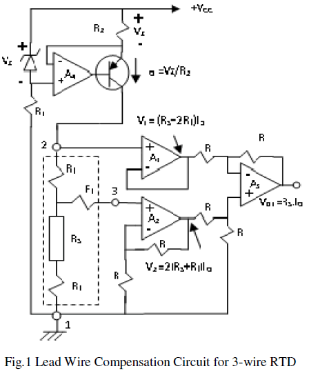
| In spite of all the advantages of resistive sensors, they pose a serious problem when applied to multi-point monitoring where the corresponding sensors have to be multiplexed to the same instrument. The resistances of the switches used in the multiplexers add to the sensor resistances leading to erroneous measurements. Moreover, the variations in the ON resistance from switch to switch tend to add different resistances to the different leads of the sensor, making the standard lead resistance compensation techniques [5], [6] unsuitable. Recently, Pradhan and Sen developed a lead resistance compensation technique [7] that converts the resistance information into equivalent voltages and use circuits to cancel the drops across the lead resistances. The circuit of [7], reproduced here in Figure 1 for ready reference, is used in the present scheme for multiplexing information received from an array of resistive sensors. |
 |
SIGNAL MULTIPLEXING |
| Multi-point measurement requires the signals to be multiplexed such that signal processing circuit should be common for all the sensors. Sensors giving direct voltage outputs like thermocouples are easy to multiplex. But resistance multiplexing is difficult due to the fact that the multiplexers themselves have channel resistances which will be added to that of the sensors. The problem can be avoided by converting the sensor resistances into equivalent voltage signals before multiplexing them to the measuring circuits. |
| The lead wire compensation scheme of Fig.1 converts information of sensor and lead resistances into suitable voltages before being processed by the electronics to produce a lead resistance free output. The RTD is excited with a constant current source (IO) built around the op-amp A4. The voltage drop V1 at terminal 2 of the RTD is buffered through the op-amp A1 and that at terminal 3 is doubled through the amplifier A2 to generate V2. Finally the output voltage VO1 is extracted by subtracting V1 from V2 by the amplifier A3, rendering VO1 independent of lead wire resistances. The expressions for V1, V2 and VO1 are identical as in [7] and are repeated below for the sake of completeness. |
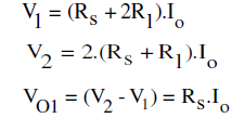 |
| Equation (3) indicates that output voltage (VO1) is proportional to the sensor resistance (RS) as IO is a constant. |
| An 8-channel multiplexing scheme for multi-point temperature measurement based on this circuit is proposed in this paper. The scheme is shown in Fig.2. Three 8-channel analog multiplexers driven by a common 3-bit selection input are used. While multiplexer #1 is used to direct the excitation current to the sensor currently being scanned, multiplexers #2 and #3 select respectively the voltages of leads 2 and 3 of the same sensor. Common selection inputs thus ensure the inclusion of only one sensor to the measuring circuit at a time. The selection inputs can be driven by a 3-bit binary counter or by three output port bits in a microprocessor based system. The channel resistance of multiplexer #1 has no effect on the performance as it is switching the output of the current source to different sensors. Multiplexers #2 and #3 connect the voltage outputs from nodes 2 and 3 of the sensor circuits to the non-inverting inputs of the amplifiers A1 and A2 respectively, having very high input impedances. Therefore, neither the switch resistances nor their variations from channel to channel have any effect on the circuit operation. Analog multiplexers used are CD4051s. |
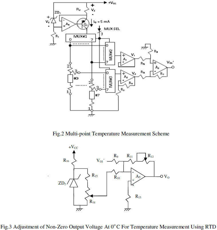 |
| The output VO1 as in Fig.1, being proportional to the sensor resistance RS, is not zero when the process temperature measured is 0 OC. An additional adder circuit as shown in Fig.3 is thus added to cancel the said non-zero value. Also as the adder circuit has a negative gain, the op-amp A3 is reversed in Fig.2 to make the final output (VO) positive. Now VO is suitable to display the temperature by a direct reading instrument. The accuracy of the system depends primarily on the constant current source. Thus it is constructed using a stable reference (LM336-2.5V) and a low drift amplifier (OP-07). In fact, all the other amplifiers and voltage references used in the circuits are OP-07s and LM336-2.5Vs only. Also the gain of the amplifier A2 should be exactly two for proper cancellation of the lead resistances. It is ensured by putting a matched resistance pair in place of R3 and R4. |
EXPERIMENTAL RESULTS |
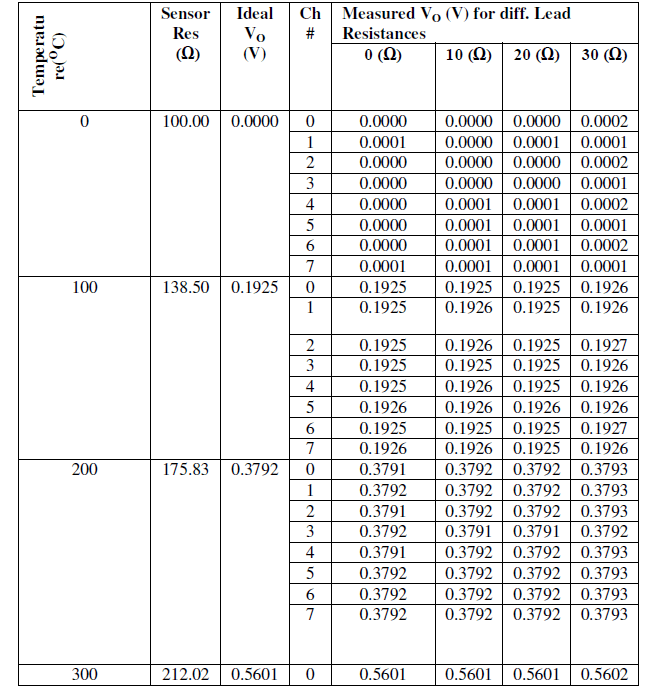
| PT100 RTD sensors are simulated through YOKOGAWA CA71 HANDY CAL Calibrator having simulation accuracy of ±(0.025% of full range + 0.1Ω for 0 to 400.00 Ω full range) [8]. Output voltage is also measured by the same calibrator having a measurement accuracy of ±(0.025% of reading + 0.2 mV for 0 to ±1.1000 V full range) [9]. Experiments are performed for different sensor resistances (corresponding to different process temperatures) in all the channels and different lead resistances added to each. A 5mA sensor excitation current is used as in [7]. Overall circuit gain is set at unity. For each channel, resistances corresponding to different sensor temperatures are simulated and voltages have been taken for four sets of lead resistances of 0 Ω, 10 Ω, 20 Ω, & 30 Ω. The data is presented in Table I. |
| From Table I it is observed that results are very close to the ideal ones. However, for quantitative analysis, worst case values for each simulated process temperature (sensor resistance) are taken from Table I and noted in Table II. It is seen from Table II that overall worst case error recorded is ±0.027%. Considering that there is a simulation accuracy of ±0.05% and measurement accuracy of ±0.052% of the calibrator, the worst case system error may be predicted as ±0.13%. |
| TABLE I |
| Measured output voltage in the circuit of fig.3. (sourcing and measurement accuracies of the calibrator are 0.05% and 0.045% of full range respectively). |
 |
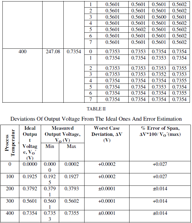 |
| From Table I it is observed that results are very close to the ideal ones. However, for quantitative analysis, worst case values for each simulated process temperature (sensor resistance) are taken from Table I and noted in Table II. It is seen from Table II that overall worst case error recorded is ±0.027%. Considering that there is a simulation accuracy of ±0.05% and measurement accuracy of ±0.052% of the calibrator, the worst case system error may be predicted as ±0.13%. |
CONCLUSION |
| The present remote multi-point temperature measurement technique is simple, uses low cost commonly available components and yet offers excellent measurement accuracy. This method can also be used for remote multi-point measurement for other process parameters where resistive sensor can be employed for basic sensing purpose, like pressure measurement by strain gauge etc. |
References |
|