ISSN ONLINE(2278-8875) PRINT (2320-3765)
ISSN ONLINE(2278-8875) PRINT (2320-3765)
| Poonam S. Deokar, Amruta R. Kaushik, Kirti B. Satale Assistant professor, Department of E&TC, KVNNIEER, Nashik, Maharashtra, India |
| Related article at Pubmed, Scholar Google |
Visit for more related articles at International Journal of Advanced Research in Electrical, Electronics and Instrumentation Engineering
Edges are boundaries between different textures. Edge also can be defined as discontinuities in image intensity from one pixel to another. Modem image processing applications demonstrate an increasing demand for computational power and memories space. Typically, edge detection algorithms are implemented using software. With advances in Very Large Scale Integration (VLSI) technology, their hardware implementation has become an attractive alternative, especially for real-time applications. The Canny algorithm computes the higher and lower thresholds for edge detection based on the entire image statistics, which prevents the processing of blocks independent of each other. The Canny edge detector has remained a standard for many years and has best performance. Direct implementation of the canny algorithm has high latency and cannot be employed in real-time applications. To overcome these, an adaptive threshold selection algorithm is proposed, which computes the high and low threshold for each block based on the type of block and the local distribution of pixel gradients in the block. Distributed Canny Edge Detection using FPGA reduces the latency significantly; also this allows the block-based canny edge detector to be pipelined very easily with existing block-based codec.
Keywords |
| Canny Edge Detector, FPGA, Latency, Threshold |
INTRODUCTION |
| Modem image processing applications demonstrate an increasing demand for computational power and memory space. Edge detection is the first step in many computer vision algorithms. It is used to identify sharp discontinuities in an image, such as changes in luminosity or in the intensity due to changes in scene structure. Typically, edge detection algorithms are implemented using software. With advances in Very Large Scale Integration (VLSI) technology, their hardware implementation has become an attractive alternative, especially for real-time applications [3]. The original Canny algorithm computes the higher and lower thresholds for edge detection based on the entire image statistics, which prevents the processing of blocks independent of each other [4]. |
| The Canny edge detector has remained a standard for many years and has best performance. Its superior performance is due to the fact that the canny algorithm performs hysteresis thresholding which requires computing high and low thresholds based on the entire image statistics. Unfortunately, this feature makes the Canny edge detection algorithm not only more computationally complex as compared to other edge detection algorithms, such as the Roberts and Sobel algorithms, but also necessitates additional pre-processing computations to be done on the entire image. As a result, a direct implementation of the canny algorithm has high latency and cannot be employed in real-time applications [2]. |
| Canny algorithm is still depending on a correct setting of the threshold greatly. They will miss some edges or detect some spurious edges when the threshold is not set a proper value. Therefore, this algorithm do not suit for mobile robot vision system in which all of the operation should be done by the robot controller and the environment changes constantly. Another shortcoming of the commonly used canny algorithm is that the computational cost of the algorithm is very high and it cannot be implemented in real time to meet the needs of mobile robot vision system [5]. |
| To overcome these shortcomings of traditional canny algorithm, an adaptive threshold selection algorithm is proposed in [2] which compute the high and low threshold for each block based on the type of block and the local distribution of pixel gradients in the block. Each block can be processed simultaneously, thus reducing the latency significantly. Furthermore, this allows the block-based canny edge detector to be pipelined very easily with existing block-based codec, thereby improving the timing performance of image/video processing systems. Most importantly, conducted conformance evaluations and subjective tests show that, compared with the frame-based canny edge detector, the proposed algorithm yields better edge detection results for both clean and noisy images. |
LITERATURE SURVEY |
| 1. Initially Direche filters have been design which detects edges in 256 X 256 images in 6s. |
| 2. Later on improved Canny-Direche filter was implemented, that was able to process 25 frames/sec at 33MHz,it used SRAM, So increased the area overhead. |
| 3. To reduce area overhead Demigny proposed new organization which reduces computation by factor of 2 , resulting in increased processing time as image size increases. |
| 4. A self adapt threshold Canny algorithm is proposed for a mobile robot system where low and high threshold values are computed. |
| 5. Recently ,the General Purpose Graphic Processing Unit (GPGPU) is used in parallel computing platform for image processing application. |
| 6. As in Canny Edge detector computation of high & low threshold depends on statistics of whole image , it decrease edge detection performance . Thus, to improve through put and decrease the Latency distributed canny edge Detector is Proposed . It uses Parallel Processing of Blocks. |
EDGE DETECTION TYPES |
| The There are many methods to make edge detection. The most common method for edge detection is to calculate the differentiation of an image. The first-order derivatives in an image are computed using the gradient, and the secondorder derivatives are obtained using the Laplacian. However, the majority of different methods may be grouped into two categories: |
| Gradient: The gradient method detects the edges by looking for the maximum and minimum in the first derivative of the image. |
| Laplacian: The Laplacian method searches for zero crossings in the second derivative of the image to find edges. An edge has the one-dimensional shape of a ramp and calculating the derivative of the image can highlight its location. |
Gradient Method |
| These are also known as 1st derivative Method. |
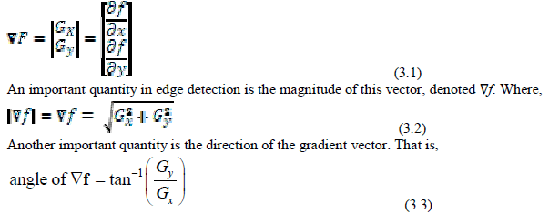 |
| Computation of the gradient of an image is based on obtaining the partial derivatives of ∂f/∂x and ∂f/∂y at every pixel location. |
| 1 Sobel Edge Detection- The operator consists of a pair of 3×3 convolution kernels. One kernel is simply the other rotated by 90°. |
| 2 Prewitt Edge Detection- Prewitt operator is similar to the Sobel operator and is used for detecting vertical and horizontal edges in images. |
| 3 Roberts Edge Detection- The Roberts Cross operator performs a simple, quick to compute, 2-D spatial gradient measurement on an image. |
Laplacian Method |
| It is also called as 2nd derivative Method. The Laplacian of a 2-D function f (x, y) is a second-order derivative defined as |
 |
Laplacian of Gaussian |
| The Laplacian is a 2-D isotropic measure of the 2nd spatial derivative of an image. The Laplacian of an image highlights regions of rapid intensity change and is therefore often used for edge detection. The Laplacian is often applied to an image that has first been smoothed with something approximating a Gaussian Smoothing filter in order to reduce its sensitivity to noise. The operator normally takes a single gray level image as input and produces another gray level image as output. The Laplacian L(x,y) of an image with pixel intensity values I(x,y) is given by: |
 |
| Since the input image is represented as a set of discrete pixels, we have to find a discrete convolution kernel that can approximate the second derivatives in the definition of the Laplacian. Three commonly used small kernels are shown in Figure.1 |
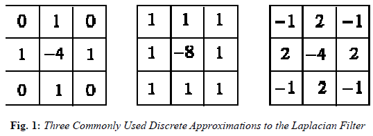 |
| Because these kernels are approximating a second derivative measurement on the image, they are very sensitive to noise. To counter this, the image is often Gaussian Smoothed before applying the Laplacian filter. This pre-processing step reduces the high frequency noise components prior to the differentiation step. In fact, since the convolution operation is associative, we can convolve the Gaussian smoothing filter with the Laplacian filter first of all, and then convolve this hybrid filter with the image to achieve the required result. Doing things this way has two advantages: Since both the Gaussian and the Laplacian kernels are usually much smaller than the image, this method usually requires far fewer arithmetic operations. |
| The LoG (`Laplacian of Gaussian') kernel can be precalculated in advance so only one convolution needs to be performed at run-time on the image. |
| The 2-D LoG function centered on zero and with Gaussian standard deviationïÿýïÿý has the form: |
 |
| As the Gaussian is made increasingly narrow, the LoG kernel becomes the same as the simple Laplacian kernels. This is because smoothing with a very narrow Gaussian ( < 0.5 pixels) on a discrete grid has no effect. Hence on a discrete grid, the simple Laplacian can be seen as a limiting case of the LoG for narrow Gaussians. |
Canny Edge Detection |
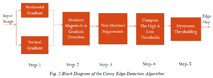
| Canny developed an approach to derive an optimal edge detector based on three criteria related to the detection performance. The model was based on a step edge corrupted by additive white Gaussian noise. A block diagram of the canny edge detection algorithm is shown in Fig. The original canny algorithm [6] consists of the following steps: |
| 1. Smoothing the input image by Gaussian mask. |
| 2. Calculating the horizontal gradient Gxand vertical gradient Gyat each pixel location by convolving with gradient masks. |
| 3. Computing the gradient magnitude G and direction θGat each pixel location. |
| 4. Applying Non-Maximal Suppression (NMS) to thin edges. |
| 5. Computing high and low thresholds based on the histogram of the gradient magnitude for the entire image. |
| 6. Performing hysteresis Thresholding. |
| 7. Applying morphological thinning on the resulting edge map. |
 |
| 1. Smoothing – Smoothing of the image is achieved by Gaussian convolutions. Blurring of the image to remove noise. |
| 2. Finding the Gradients- Gradient calculation is performed using Finite-impulse-Response (FIR) gradient masks designed to approximate 2D sample version of partial derivative of Gaussian Function. The size of gradient mask used by canny edge detector is function of standard deviation. |
| 3. Calculation of Gx and Gy: The actual images are always discrete; we define the direction as vertical, horizontal, left-diagonal and right-diagonal of the 3x3 adjacent window of current pixel.The first-derivative of each direction is then calculated by |
| E = ( { -1,1} )3 X 3 X H(i,j)3 X 3 (3.9) |
| Using a {-1,+1} operator to the adjacent pixels along each direction, we get EV, EH, EDL and EDR, the results of equation in vertical, horizontal, left-diagonal and right-diagonal directions. The magnitude of gradient of current pixel is the maximum of |EH|, |EV|, |EDR|, |EDL|, and the direction of gradient is one of the four directions corresponding to the maximum of |EH|, |EV|, |EDR|, |EDL|. |
| |grads (H(I,j)) | =max { |EH|, |EV|, |EDR|, |EDL| } (3.10) |
| Θ = Arg (max { |EH|, |EV|, |EDR|, |EDL| }) (3.11) |
| Since 3x3 convolutions are used to calculate the gradients, neighboring 8 pixels are required. FIFO buffers are employed to store the output pixels. |
| 4. Non-Maximal Suppression - Once the direction of the gradient is known, the pixel that has no local maximum gradient magnitude is eliminated. If the pixel’s gradient direction is one of 8 possible main directions (0º, 45º, 90º, 135º, 180º, 225º, 270º, 315º), the gradient magnitude of this pixel is compared with two of its immediate neighbors along the gradient direction and the gradient magnitude is set to zero if it does not correspond to a local maximum. For the gradient directions that do not coincide with one of the 8 possible main directions, an interpolation is done to compute the neighboring gradients. |
| 5. Threshold Calculation - Computing high and low thresholds based on the histogram of the gradient magnitude for the entire image. The high threshold is computed such that a percentage p1 of total pixel in the image would be classified as Strong edge. The high threshold corresponds to the point at which value of gradient magnitude is Cumulative distributive function (CDF) equals to 1- p1. The low threshold is calculated as percentage p2 of high threshold. |
| 6. Hysteresis Threshold - It is used to determine the edge map. If the gradient magnitude of pixel is greater than high threshold then this pixel is considered as strong edge. If the gradient magnitude of pixel is between high and low threshold then this pixel is considered as weak edge. |
Distributed Canny Edge Detection |
| The Canny edge detection algorithm operates on the whole image and has a latency that is proportional to the size of the image. While performing the original canny algorithm at the block-level would speed up the operations, it would result in loss of significant edges in high-detailed regions and excessive edges in texture regions. Natural images consist of a mix of smooth regions, texture regions and high-detailed regions and such a mix of regions may not be available locally in every block of the entire image. In [6], distributed canny edge detection algorithm is proposed, which removes the inherent dependency between the various blocks so that the image can be divided into blocks and each block can be processed in parallel. |
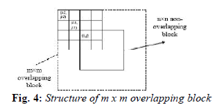
| In the proposed distributed version of the Canny algorithm, the input image is divided into m × n overlapping blocks, and the blocks are processed independent of each other. To prevent edge artifacts and loss of edges at the boundaries, adjacent blocks overlap by (L-1)/2 pixels for L× L gradient mask. However, for each block, only edges in the central n × n (where n= m-L+1) non-overlapping region are included in the final edge map. In the proposed algorithm, Steps 1 to 3 and Steps 5 to 7 are the same as in the original canny algorithm except that these are now applied at the block level. The high and low gradient threshold selection step of the original Canny (Step 4) is modified to enable block-level processing. Analysis of natural images showed that a pixel with a gradient magnitude of 4 corresponds to a psychovisually significant edge. Also, a pixel with a gradient magnitude of 2 and 6 corresponds to blurred edges and very sharp edges, respectively. The proposed threshold selection algorithm was designed based on these observations and is as shown below: |
| 1) Calculating the horizontal gradient Gxand vertical gradient Gyat each pixel location by convolving with gradient masks. |
| 2) Computing the gradient magnitude G and direction θGat each pixel location. |
| 3) Applying Non-Maximal Suppression (NMS) to thin edges. |
| 4) Parallel block-level processing without degrading the edge detection performance. |
| 5) Performing hysteresis thresh holding to determine the edge map. |
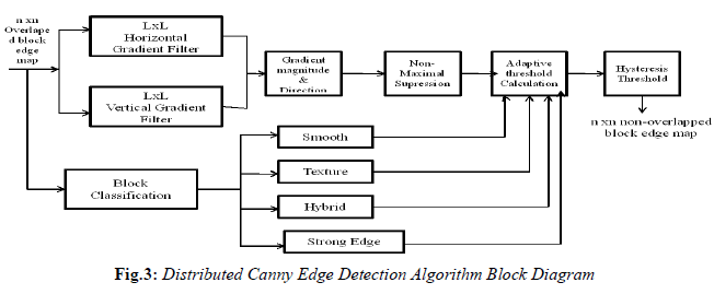 |
| Natural images consist of a mix of smooth regions, texture regions and high-detailed regions and such a mix of regions may not be available locally in every block of the entire image. The input image is divided into m×m overlapping blocks. The adjacent blocks overlap by (L − 1)/2 pixels for a L × L gradient mask. |
 |
DISTRIBUTED CANNY EDGE ALGORITHM USING FPGA |
| The Embedded system for implementing the distributed canny edge detection algorithm based on an FPGA platform. It is composed of several components, including an embedded micro-controller, a system bus, peripherals & peripheral controllers, external Static RAMs (SRAM) & memory controllers, and an intellectual property (IP) design for the proposed distributed Canny detection algorithm. The embedded micro-controller coordinates the transfer of the image data from the host computer (through the PCIe (or USB) controller, system local bus, and memory controller) to the SRAM; then from the SRAM to the local memory in the FGPA for processing and finally storing back to the SRAM. Xilinx and Altera offer extensive libraries of intellectual property (IP) in the form of embedded micro-controllers and peripherals controller [1]. |
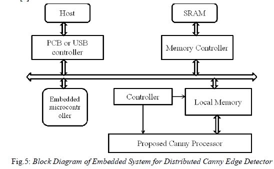 |
| FPGA required to implement distributed canny edge detector algorithm consists of q processing units (PU) and external dual-port Static RAMs (SRAMs). Each PU consists of p computing engines (CE), where each CE processes an m×moverlapping image block and generates the edges of an n×nblock, where m = n+L+1 for an L×L gradient mask. The dataflow through this architecture is as follows. For each PU, the SRAM controller fetches the input data from SRAM and stores them into the input local memory in the PU. The CEs read this data, process them and store the edges into the output local memory. Finally, the edges are written back to the SRAM one output value at a time from the output local memory. |
| FPGA Architecture consists of following blocks: |
Computing Engine (CE) |
| Each CE processes an m × m overlapping image block and generates the edges of an n × n non-overlapping block. The computations that take place in CE can be broken down into the following five units: |
| 1) Block classification. |
| 2) Vertical and horizontal gradient calculation as well as magnitude Calculation. |
| 3) Directional non-maximum suppression. |
| 4) High and low threshold calculation. |
| 5) Thresh holding with hysteresis. |
| The edge detection computation can start after n m × m overlapping block is stored in CE’s local memories. In addition, in order to compute the block type, vertical gradient and horizontal gradient in parallel, the m × m overlapping block is stored in three local memories, marked as local memory 1, 2 and 3. |
| If, Th-h: High threshold ,Th-l: L ow threshold, Gx: Gradient in x direction ,Gy: Gradient in y direction ,M:Magnitude ,mag_max: Maximum magnitude, mag_min: Minimum magnitude |
Block Classification |
| The m×moverlapping block is stored in the CE’s local memory 1 and is used for determining the block type. The architecture for the block classification unit consists of two stages. Stage 1 performs pixel classification while stage 2 performs block classification. |
| For pixel classification, the local variance of each pixel is utilized. The computation is done using one adder, two accumulators, two multipliers and one square. Then two counters are used to get the total number of pixels for each pixel type. The output of counter 1 gives C1, the number of uniform pixels, while the output of counter 2 gives C2, the number of edge pixels. The block classification stage is initialized once the C1 and C2 values are available. Outputs are used as the control signals of MUX 1 and MUX 2 to determine the value of P 1 . Finally, the P 1 value is compared with 0 to produce the enable signal, marked as EN.Outputs are used as the control signals of MUX 1 and MUX 2 to determine the value of P 1 . Finally, the P 1 value is compared with 0 to produce the enable signal, marked as EN. If the P 1 value is larger then 0, then EN signal enables gradient calculation, magnitude calculation, directional non-maximum suppression, high and low threshold calculation and thresholding with hysteresis units. Otherwise, these units do not need to be activated. |
Gradient and Magnitude |
| Block classification unit and gradient and magnitude unit are independent of each other so works in parallel. It consists of three computational part one address and time controller used for addresses and control signal for computation. |
| For vertical and horizontal gradient calculation input block image is convolved with 2-D horizontal and vertical gradient masks. These are separable, so 2-D convolution is obtained by separate 1-D convolution. In FPGA Xilinx FIR IP core is used, which provides highly parameterizable, area efficient implementation that utilizes the symmetry characteristics of coefficient. |
| The result of vertical and horizontal gradient calculations is stored in local memory. With Xilinx IP core which provides pipeline mode, unsigned fraction format was used. The maximum and minimum values of magnitude marked as mag_max and mag_min are output of this block. It is used as a input for threshold calculation unit. |
Directional Non Maximal Suppression |
| Horizontal and vertical gradient magnitudes are fetched from local memory and used as input to NMS unit. It computes gradient direction at each pixel.Gradient magnitudes of gradient magnitudes of four nearest neighbors along the direction are selected to compute two intermediate gradients. Gradient magnitudes of four nearest neighbors along the direction are selected to compute two intermediate gradients. |
| The final gradient magnitude after directional NMS (marked as Mag_NMS(x, y) is stored back into local memory and used as the input for the hysteresis thresholding unit. |
Calculation of Thresholds |
| This unit can be pipelined with the directional NMS unit. the p11 value, which is determined by the block classification unit, the mag_max, and mag_min, which are determined by the gradient and magnitude calculation unit, are also the inputs for this unit. The adders and shifters are used to obtain the reconstruction levels Ri, and the comparators (1 to 8) and counters (1 to 8) are used to count the corresponding numbers of pixels. |
| The p1 value, which is determined by the block classification unit, is multiplied with the total number of pixels in the block. The obtained pixel number, noted by NoPixels_P1, is compared with each NoPixels_Ri in order to select the level i. According to the selected level i, mag_max, and mag_min, the arithmetical unit can compute the corresponding Ri, which is the high threshold ThH. low threshold is computed as 40% of the high threshold. |
Thresholding with Hysteresis |
| The gradient magnitude of each pixel after directional NMS is fetched from local memory 1 and used as input to the thresholding Unit., Output of threshold calculation unit, are also the inputs for this unit. f1represents a strong edge pixel while f2 represents a weak edge pixel. If any of the neighbors of the current pixel is a strong edge pixel, the center weak edge pixel is then considered as a strong edge pixel; otherwise, it is considered as a background non-edge pixel. The latency between the first input and the first output is 10 cycles and the total execution time for the hysteresis thresholding unit is m×m+10 cycles. |
CONCLUSION |
| Distributed Canny Edge Detector does not need manual threshold calculation; it can be implemented for real time application. Proposed method presents non uniform quantized histogram calculation method in order to reduce hysteresis threshold selection cost. As a result, computation cost of proposed algorithm is lo was compared to original canny edge detection algorithm. Distributed Canny edge detection algorithm that results in a significant speed up without sacrificing the edge detection performance. In order to improved results system is implemented in FPGA to support fast Real-time Edge detection of images and videos. |
References |
|