ISSN ONLINE(2319-8753)PRINT(2347-6710)
ISSN ONLINE(2319-8753)PRINT(2347-6710)
Saivignesh H 1, Mohamed Shimil M 1, Nagaraj M 1, Dr.Sharmila B2, Nagaraja pandian M3
|
| Related article at Pubmed, Scholar Google |
Visit for more related articles at International Journal of Innovative Research in Science, Engineering and Technology
Intelligent instruments are used in every part of our lives. It won’t take much time to realize that most of our tasks are being done by Electronics. They will perform one of the most complicated tasks that a person does in a day, that of driving a vehicle. As the days of manned driving are getting extremely numbered, so are those of traffic jams, dangerous and rough drivers and more importantly, accidents. According to Mr Willie D. Jones in the IEEE SPECTRUM magazine (September 2001), a person dies in a car crash every second. Automation of the driving control of vehicles is one of the most vital needs of the hour. This technology can very well implement what was absent before, controlled lane driving. The ultimate aim of this project is to automatically control the speed of the vehicles at speed restricted areas such as school and hospital zone etc. This project is mainly developed to avoid accidents due to high speed vehicles and also to enable the public to cross the road without any danger from high speed vehicles. Usually the drivers drive the vehicles at high speed without considering the public in speed limited areas too. Even though the traffic police control them we cannot achieve full response from them. Also it is not possible to monitor those areas at all time to regulate their speed. Thus this project paves way for controlling the speed of the vehicles within certain limit in those restricted zones without the interruption of the drivers. Here we use RF communication method for controlling purpose. In order to implement this in public then we want to attach the RF receiver along with the vehicle and the Transmitter with these Zones. These transmitters are programmed to send the coded signals continuously with certain delay in between. Whenever the vehicles enter into these zones their receivers will receive this code and then the speed of the vehicles is controlled automatically by taking control action in the throttle valve. This will reduce the over speed to the desired speed limit.
Keywords |
| DAQ, Throttle Valve, ECU, MAF sensor, Speed limiting zones |
INTRODUCTION |
| It is known that road accidents are increasing day by day. Most of these road accidents are caused because the automobiles are driven at high speeds even in the places where sharp turnings and junctions exist. Running the automobiles even at those places is the main cause for the accidents. Reduction of number of such accidents is the prime step needed to be taken. Many systems have been developed to prevent these road accidents. One of them is Cruise control system (CC) that is capable of maintaining speed defined by the driver and its later evolution version Adaptive Cruise Control (ACC) that keeps the automobile at safer distance from the preceding vehicle. But these systems have no capability to detect the curved roads where the speeds of the automobiles have to be lowered to avoid the accidents. Later curve warning systems (CWS) have been developed to detect the curved roads by using Global Positioning System (GPS) and the digital maps obtained from the Geographical Information Systems (GIS) to assess threat levels for driver if approaching the curved road quickly. But these maps need to be updated regularly and are not useful if there are unexpected road diversions or extensions etc. Here we propose a dynamic model where the system controls the speed of the automobile according to the data in the frame that is transmitted by the RF transmitter fixed to the nearby poles. This is based on the work done by Sato et al. (describes an Advanced Driver Assistance System (ADAS)) and Joshua Pérez’ team (describes an RFID-Based Intelligent vehicle speed controller) where passive RF transceivers are arranged in the road close to the position of real traffic signals. This model can also be better utilized to improve the fuel efficiency by imposing the maximum speed limit on the automobiles at which the mileage will be more. Paper is organized as follows. Section II describes the related work in the area. The block diagram is given in Section III. Section IV presents the existing methodology. Section V presents the model designing and description. Section VI depicts the simulation result. Finally, Section VII presents the conclusion. |
II. RELATED WORK |
| An autonomous intelligent cruise control (AICC) system for automatic vehicle following was developed [1]. The experimental architecture of an integrated system to prevent driver from taking a curve with a dangerous speed is shown [2]. An in-vehicle signing system was built and assessed that uses general-purpose RFID tags as digital traffic signs, and a field test was conducted using tags installed on a road to verify whether the system worked effectively or not [3]. A mathematical tool to build a fuzzy model of a system where fuzzy implications and reasoning are used is presented [4]. Fuzzy control of a model car is presented and Fuzzy control rules are derived by modelling an expert's driving actions. Experiments are performed using a model car with a sensing unit and a micro-computer [5]. |
III. BLOCK DIAGRAM AND DESCRIPTION |
| The block diagram and its description are shown in Fig. 1. It has two sections. |
| a) Transmitting Unit |
| b) Vehicle Speed Control and Monitoring Unit |
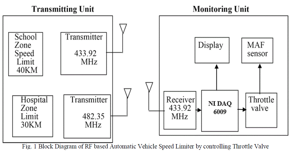 |
| a) Transmitting Unit The Transmitting unit consist of a transmitter which has been set to individual frequencies with respect to school zones or hospital zone etc. The transmitting range will be set about 500 meters to 1 kilometre in radius or as per the zone’s requirement. |
b) Vehicle Speed Control and Monitoring Unit |
| In this unit, the moment at which the vehicle receives the signal, the control action takes place by the NI DAQ 6009, which will control the position of the throttle valve by limiting the maximum speed of the vehicle. And also the display which will be present inside the vehicle will display the name of the respective zone within which the vehicle is present. |
IV. EXISTING METHODOLOGY |
| In general, the speed of the automobile is varied according to the accelerator’s Pedal position. The variation in the Pedal position is fed to the Electronic Control Unit (ECU) .ECU determines the position of the throttle based on the accelerators pedal position and the inputs received from the other sensors. Adjustment of throttle position causes the change in the variation of automobiles speed. Such type of hardware scheme is shown in figure 2. Whereas in the proposed automatic vehicle speed controller model accelerator pedal position is given to the microcontroller unit and then it is fed to the Electronic Control Unit. If the automobile is in the active mode, NI DAQ 6009 controls the position of the throttle valve by limiting the maximum speed of the vehicle . |
METHODS OF THROTTLE POSITION CONTROL |
| The methods of controlling has been modified into two types based on the design of throttle system namely |
| a) Based on Drive by Wire |
| b) Based on Electronic Throttle |
| a) Based on Drive by Wire |
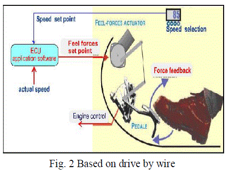 |
| It is an automobile technology which electronically "connects" the accelerator pedal to the throttle by mechanical linkage. Fig. 2 shows the schematic diagram on drive by wire system. So in order to control the position of the throttle valve is impossible because it is linked by a mechanical linkage directly from the gas pedal. So in order to control the speed of vehicle, an additional throttle valve will be placed in front of the first throttle valve. The additional throttle valve will be controlled by the NI DAQ 6009 by controlling the position of the additional throttle valve to limit the maximum speed of the vehicle in the required zones. Thus an additional throttle valve should be used in Drive by Wire system to control the maximum speed limit of the vehicles. |
b) Based on Electronic Throttle |
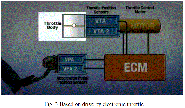 |
| It is an automobile technology which electronically "connects" the accelerator pedal to the throttle, replacing a mechanical. Fig. 3 shows schematic diagram of drive by electronic throttle system. In this type of system, the position of the throttle valve can be controlled directly by NI DAQ 6009. There is no need of additional throttle valve as mention in drive by wire method. Thus, when the vehicle enters the speed limit zones, the control action takes place and the maximum vehicle speed is automatically controlled. |
V. MODEL DESIGNING AND DESCRIPTION |
| The NI DAQ USB-6009 is designated with 8 analog inputs and 2 analog outputs. Although, this DAQ consists of digital input-output ports, analog ports are most desired as of now, as they are the required ports to access the voltage coming in from the temperature sensor After successfully initializing the DAQ assistant, following control panel can be observed, where all the required control logic can be given-in and also, respective indicators can be allotted, so as to view their working status. For this current project, two terminals are required for the output to be drawn out and displayed, one being the output voltage terminal, and the other being the corresponding ground terminal. Now referring to above figure, a ground terminal must be selected and the ground terminal respective to the output voltage of the current transformer must be coupled. Correspondingly, the output voltage terminal has to be connected to any of the analog input Terminals of the DAQ, thereby concluding the process of making the hard-wire connections, to enable the opportunity to display the output and thereby proceed with control logic system. The above described process, at the end would appear as shown in the following figure. Another important connection of the DAQ USB-6009 with the PC has to be made using the Provided cable, through which the communication between the PC and the DAQ would be Possible to display the output and to further take any control action. |
| The entire control logic to have been implemented in the project was made possible with the use of LabVIEW programming with its simple block-diagram approach in building the entire logic. Viewing it step-wise, the output which is read by the DAQ is the angular position of the throttle valve based on the running speed of the vehicle due to applied acceleration |
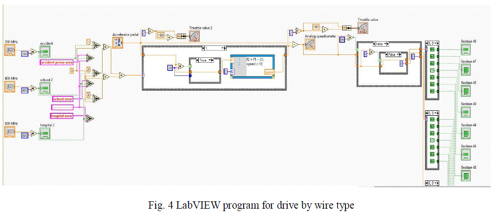 |
| The block diagram of drive by wire is shown in the Fig. 4 the above program is run in the block diagram panel for simulation purpose. Two throttle valves are used in this method one is primary throttle valve 1 and the additional throttle valve is used to limit the speed of the vehicle in required zones. |
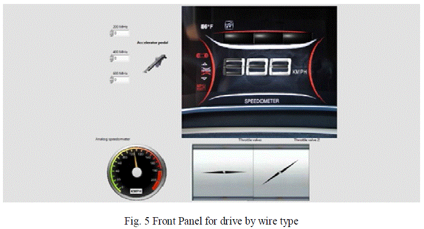 |
| The Fig. 5 shows the Front panel of the drive by wire type, which simulates the work of acceleration position, speedometer and also the position of two throttle valves 1 & 2. When the vehicle is not present in the required speed limiting zone, the throttle valve never changes its position whereas throttle valve 1 changes it position based on accelerator pedal position. In this mode, the speed is not limited. |
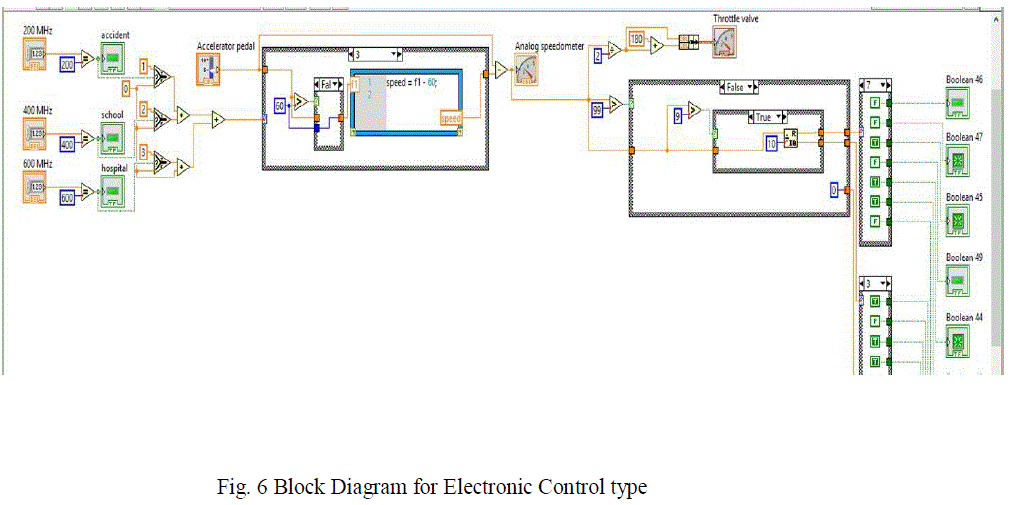 |
| The block diagram of electronic control type of throttle is shown in the Fig. 6, the above program is run in the block diagram panel for simulation purpose. In this mode only single throttle valve is used which can be controlled when it reaches the speed limiting zone. |
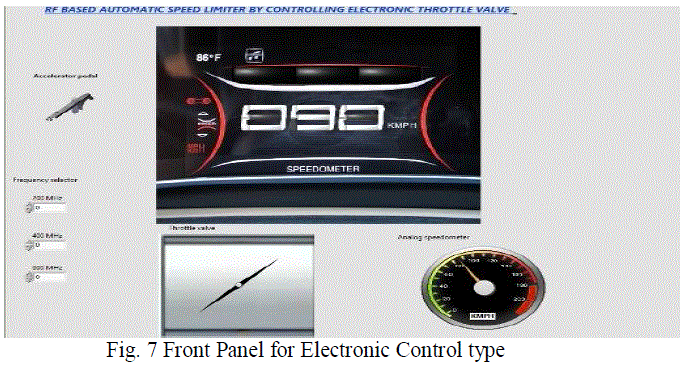 |
| The Fig. 7 shows the Front panel of electronic control type, which simulates the work of acceleration position, speedometer and also the position of two throttle valve. When the vehicle is not present in the required speed limiting zone, the throttle valve changes it position based on accelerator pedal position. In this mode, the speed is not limited. But when it reaches the respective zones, the position of the throttle valve is limited when the vehicle exceeds the speed. |
VI. SIMULATION RESULT |
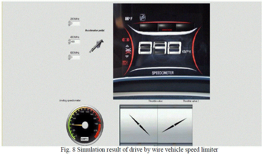 |
| The Fig. 8 shows the simulation result for the drive by wire type in which when the vehicle reaches the speed limiting zone, the secondary throttle valve1 gets activated and its position is changed to control or limit the desired speed as per the required zone. |
VII. CONCLUSION |
| In this paper we presented a new design to control the speed of the automobiles. We have presented a theoretical study on our proposed design. In our theoretical study, only one vehicle is considered. In normal driving situations, we can expect other vehicles circulating nearby and possibly blocking or attenuating RF signals. In this aspect, more study is needed. |
ACKNOWLEDGEMENT |
| We would like to thank our Management, Director Academics, Principal, Head of the Department of Electronics and Instrumentation Engineering and Faculty Members of the EIE Department of Sri Ramakrishna Engineering College, Coimbatore for their support throughout our project. |
References |
|