ISSN ONLINE(2278-8875) PRINT (2320-3765)
ISSN ONLINE(2278-8875) PRINT (2320-3765)
Sheela Joseph1,Akhil S2, Akhil K. Narayanankutty3, Amalraj P.M.4,Aleena Paul K.5
|
| Related article at Pubmed, Scholar Google |
Visit for more related articles at International Journal of Advanced Research in Electrical, Electronics and Instrumentation Engineering
This paper is based on a project designed to ensure the safety of pedestrians and passengers during harsh driving conditions. It includes two different techniques to ensure the safety of vehicles and pedestrians. The heart of this project is the ATmega 16A microcontroller. It’s a low power 8-bit CMOS microcontroller based on AVR enhanced RISC architecture. The microcontroller takes in input from different sensors and adjusts the performance of the vehicle accordingly. The various techniques used in the system are traffic alert system and anti-collision system. The Traffic Alert System transmits traffic signals at required parts of the road. The RF transmitter fixed on roadsides emits RF signals corresponding to the sign boards. RF receiver in the vehicle receives this code and sends it to the microcontroller. Microcontroller then decodes the signals and displays the traffic signal in the LCD screen. The Anti- Collision Circuit warns the driver when the vehicle is dangerously close to other objects. An IR transmitter-receiver pair is used here. The IR LED emits IR rays which get reflected back after hitting the surrounding objects. These reflected rays are collected by the IR receiver which then sends it to the microcontroller. Microcontroller makes use of this intensity to calculate the distance to the object. It then warns the driver if the object is too close.
Keywords |
| ATmega 16A, Road Safety, RF Transceiver, Microcontroller, Anti-Collision, Rx/Tx 434 |
INTRODUCTION |
| This paper deals with a topic of much contemporary relevance. It proposes a unique and economical method for improving the safety of our roads.Road accidents are a leading cause of death and injury worldwide. By 2020, the World Health Organization (WHO) projects that road crash injuries will be the third highest threat to public health, outranking other serious public health problems such as tuberculosis. One of the major causes for road accidents is ignorance of traffic signs and hazardous driving conditions. Nearly 1.3 million people die in road crashes each year, on average 3,287 deaths a day. An additional 20-50 million are injured or disabled. Poor road infrastructure, failure to comply with speed limits, growing drinking and driving habits, and refusal to use proper motorcycle helmets and use child car seats, are among the main factors contributing to deaths from road crashes, WHO said in its report on ‘Decade of Action for Road Safety 2010-2011’. It underlines the fact that we require better technologies to ensure the safety of our roads. The paper suggests a novel idea for improving the safety of our roads. It includes anti-collision system for ensuring safe driving distance and a wireless system to send traffic signs to the vehicle display.It aims at tackling one of the major reasons for increasing number of accidents. Traffic signals may pass unnoticed due to bad weather conditions, driver’s ignorance or other such distractions. This also include vital sign boards such as hair pin curves, gutters etc. This system ensures that no vital sign boards will go unnoticed, whatever the conditions be. It also includes an anti-collision system which ensures safe driving distance between vehicles. It serves a dual purpose of parking assist when connected in the rear side of the vehicle. |
INTERFACING RF MODULE |
| In the last years, RFID technology has been gradually incorporated to commercial transportation systems [1]. A wellknown example is the RFID-based highway toll collection systems which are now routinely employed in many countries, like the Telepass system in Italy or the Autopass system in Norway. Other uses include monitoring systems to avoid vehicle theft [2], access control to car parking or private areas [3].The prototype is using the radio frequency of 434 MHz compared to the range of about 3 kHz to 300 GHz of frequency which have been reserved for the RF theoretically [4]. This section gives an idea about interfacing the Rx/Tx 434 module used in this system. It explains in detail about the ICs used for the coding and decoding of data. |
A. RF Module |
| The RF module, as the name suggests, operates at Radio Frequency. In this RF system, the digital data is represented as variations in the amplitude of carrier wave. This kind of modulation is known as Amplitude Shift Keying (ASK). Transmission through RF is better than IR (infrared) because of many reasons [5]. Firstly, signals through RF can travel through larger distances making it suitable for long range applications. Also, while IR mostly operates in line-of-sight mode, RF signals can travel even when there is an obstruction between transmitter & receiver. Next, RF transmission is more strong and reliable than IR transmission. RF communication uses a specific frequency unlike IR signals which are affected by other IR emitting sources. |
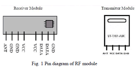
| The RF module comprises of an RF Transmitter and an RF Receiver. The transmitter/receiver (Tx/Rx) pair operates at a frequency of 434 MHz. An RF transmitter receives serial data and transmits it wirelessly through RF through its antenna connected at pin4. The transmission occurs at the rate of 1Kbps - 10Kbps.The transmitted data is received by an RF receiver operating at the same frequency as that of the transmitter. The RF module is often used along with a pair of encoder/decoder [6]. The encoder is used for encoding parallel data for transmission feed while reception is decoded by a decoder. HT12E-HT12D, HT640-HT648, etc. are some commonly used encoder/decoder pair ICs. The pin diagram [8] of the module is shown in Fig. 1. |
 |
B. Encoder IC HT 12E |
| The 212 encoders are a series of CMOS LSIs for remote control system applications [9]. They are capable of encoding information which consists of N address bits and 12_N data bits. Each address/ data input can be set to one of the two logic states. The programmed addresses/data are transmitted together with the header bits via an RF or an infrared transmission medium upon receipt of a trigger signal. The capability to select a TE trigger on the HT12E or a DATA trigger on the HT12A further enhances the application flexibility of the 212 series of encoders. The HT12A additionally provides a 38 kHz carrier for infrared systems. |
| The 212 series of encoders begin a 4-word transmission cycle upon receipt of a transmission enable signal. This cycle will repeat itself as long as the transmission enable (TE or D8~D11) is held low. Once the transmission enables returns high the encoder output completes its final cycle and then stops. The address pins A0-A7 are used to ensure that the data reaches the intended receivers only. But in this case, the address pins A0-A7 are simply grounded. |
C. Decoder IC HT 12D |
| The 212 decoders are a series of CMOS LSIs for remote control system applications [10]. They are paired with Holtek’s 212 series of encoders. For proper operation, a pair of encoder/decoder with the same number of addresses and data format should be chosen. The decoders receive serial addresses and data from a programmed 212 series of encoders that are transmitted by a carrier using an RF or an IR transmission medium. They compare the serial input data three times continuously with their local addresses. If no error or unmatched codes are found, the input data codes are decoded and then transferred to the output pins. The VT pin also goes high to indicate a valid transmission. The 212 series of decoders are capable of decoding information that consists of N bits of address and 12_N bits of data. Of this series, the HT12D is arranged to provide 8 address bits and 4 data bits, and HT12F is used to decode 12 bits of address information. |
| The 212 series of decoders provides various combinations of addresses and data pins in different packages so as to pair with the 212 series of encoders. The decoders receive data that are transmitted by an encoder and interpret the first N bits of code period as addresses and the last 12_N bits as data, where N is the address code number. A signal on the DIN pin activates the oscillator which in turn decodes the incoming address and data. The decoders will then check the received address three times continuously. If the received address codes all match the contents of the decoder’s local address, the 12_N bits of data are decoded to activate the output pins and the VT pin is set high to indicate a valid transmission. This will last unless the address code is incorrect or no signal is received. The output of the VT pin is high only when the transmission is valid. Otherwise it is always low. These decoder ICs have a wide range of operating voltages ranging from 2.4V to 12V. Low power and high noise immunity CMOS technology is used. The received codes are checked three times to ensure error-free reception. They find applications in burglar alarm systems, smoke and fire alarm systems, car door controllers etc. |
CIRCUIT DIAGRAMS AND OPERATION |
| One of the major advantages of this system is its simple circuit and working principle. The circuit is divided into two parts. First one is the microcontroller section which is kept inside the automobiles and second is the RF transmitter section kept on roadsides. Both of them are discussed in detail in coming sections. |
A. Anti-collision System |
| This arrangement serves mainly two purposes. It helps the driver to park the vehicle without bumping into other vehicles or corridors. It also warns the driver when an automobile is dangerously close to his vehicle during a drive. |
 |
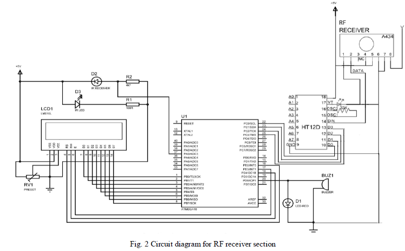
| This circuit uses matched IR transmitter-receiver pair to accurately measure the clearance distance in front of the vehicle. The IR rays emitted by the IR LED hit the target and get reflected back to the receiver. This cause a current flow in the receiver circuit proportionate to the intensity of incident IR rays. A series resistance connected in series with the receiver converts this current flow to an equivalent voltage drop. So the more nearer the object is, greater will be the intensity of incident IR rays and thus the voltage drop. So in effect, the IR transceiver module coverts the clearance distance to an equivalent voltage drop. The drop across the series resistance is fed to the third ADC pin of ATmega 16A. The microcontroller converts this analog value to an equivalent digital signal. By suitable calibration, this will provide the accurate clearance in front of the vehicle and this clearance is displayed in the LCD screen continuously. The system is configured in such a way that whenever this distance goes below a predefined value, audible and visualwarnings are produced. The circuit of receiver module that should be kept inside the automobiles is given in Fig. 2. It consists of the microcontroller ATmega 16A, IR transceiver, LCD screen, decoder IC and the RF receiver. |
 |
| The major advantage of this system is that the receiver section has no connection with the internal circuitry of the vehicle. Hence it can be integrated onto any of the existing vehicles without any modifications to the vehicle. This makes the system highly adaptable. Apart from the receiver section mounted on the vehicle, the circuit has a transmitter section which has to be placed near roadsides. |
B. Traffic Alert System |
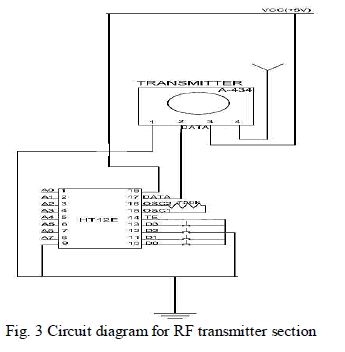
| The core of this system is an RF module. RF transmitters are placed besides traffic sign boards. They transmit data code serially to the receiver placed inside the vehicles which then get passed onto the microcontroller where it gets decoded. The required information is then displayed in an LCD screen.For understanding the working of RF transmitter section, one should have a basic knowledge about radio frequency waves and their propagation. Radio waves are a type of electromagnetic radiation with wavelengths in the electromagnetic spectrum longer than infrared light. Radio waves have frequencies from 300 GHz to as low as 3 kHz. Like all other electromagnetic waves, they travel at the speed of light. Different frequencies of radio waves have different propagation characteristics in the Earth's atmosphere; long waves may cover a part of the Earth very consistently, shorter waves can reflect off the ionosphere and travel around the world, and much shorter wavelengths bend or reflect very little and travel on a line of sight. In order to receive radio signals, for instance from AM/FM radio stations, a radio antenna must be used. However, since the antenna will pick up thousands of radio signals at a time, a radio tuner is necessary to tune in to a particular frequency (or frequency range). This is typically done via a resonator (in its simplest form, a circuit with a capacitor and an inductor). The resonator is configured to resonate at a particular frequency (or frequency band), thus amplifying sine waves at that radio frequency, while ignoring other sine waves. Usually, either the inductor or the capacitor of the resonator is adjustable, allowing the user to change the frequency at which it resonates. The RF transmitter (TX 434) used in this project works at 434MHz. Different binary codes is assigned to each and every traffic signs. A 4 way DIP switch is used to simulate all these signs in this project. The code is fed parallel to the encoder IC HT 12E, which converts it to a serial bit stream and sends to the RF transmitter. These RF transmitters kept at the roadsides transmit the data wirelessly to approaching vehicles. As RF waves have very good range, notifications are given well before the approach of traffic signals. Fig. 3 shows the circuit of RF transmitter used in the system. |
 |
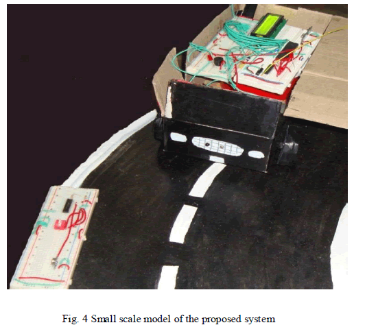
| A scaled version of the proposed system was implemented and is shown in Fig. 4. It was able to detect the RF signals from fairly good distances with 100% accuracy. |
CONCLUSION |
| The paper presents a low-cost and simple system to ensure the safety of passengers and pedestrians. It certainly provides a hope for bringing down the alarming rate of road accidents. The proposed system is capable of simply displaying the traffic signals in an LCD screen inside the vehicle. In future, provisions may be included to cut out the fuel supply to the engine to provide a smooth deceleration if the speed of the vehicle exceeds a threshold value. |
ACKNOWLEDGMENT |
| We hereby express our sincere gratitude to the Head of the Department of Electrical And Electronics Engineering, Prof. K. Radhakrishnan for providing us with the necessary arrangement for the completion of our project. We also thank our faculty advisor Prof. Bindu Elias for her valuable guidance. We express our sincere gratitude to our guide Asst. Prof. Jeena Joy, Department of Electrical And Electronics Engineering, without whose valuable guidance and support the project would not have been a success. We thank her for the good will and encouragement extended to us. Our heartfelt gratitude to Asst. Prof. Eldhose K.A. and Assoc. Prof. Sini Paul, Department of Electrical& Electronics Engineering, for their constant support and guidance. |
References |
|