ISSN ONLINE(2278-8875) PRINT (2320-3765)
ISSN ONLINE(2278-8875) PRINT (2320-3765)
Nidhish G. Mishra1, A. A. Shaikh2,
|
| Related article at Pubmed, Scholar Google |
Visit for more related articles at International Journal of Advanced Research in Electrical, Electronics and Instrumentation Engineering
A general practice to protect the power electronics converters nowadays is to disconnect the DFIG (Doubly-fed Induction Generator) wind generator from the grid or use crowbar arrangements in case of voltage dip during a fault. It takes some time to reconnect the generator back to the grid. Disconnection of such a large power can severally affect power system operation during the fault and post-fault conditions. In this paper the behaviour of DFIG is investigated, when a D-STATCOM (Distribution Static Compensator) is used to provide low voltage ride through capability.
Keywords |
| Crowbar, DFIG, D-STATCOM, FACTS, PCC, LVRT |
INTRODUCTION |
| Amongst the available types of wind turbine generators, DFIG is gaining more attention and application in wind energy systems due to its ability to extract maximum power [1]. In case of the voltage dip, a general practice nowadays is to disconnect the DFIG wind turbine from the grid in case of a fault to protect back to back connected converters from high flow of rotor current the and it takes some time to reconnect the turbine back to the grid. Disconnection of such a large power in future can severally affect power system operation during the fault and post-fault conditions. In this situation it will not support the voltage and frequency of the grid and system stability will be adversely affected. In crowbar arrangement, the rotor is disconnected from the rotor side converter and is short-circuited through an external resistance [2]. While the crowbar is activated, Vdr and Vqr are set to zero and external resistance is added to the rotor circuit. In this situation it will not support the voltage and frequency of the grid and system stability will be adversely affected. Fully controllable switch e.g. IGBTs are used to deactivate the crowbar as soon as possible so that the machine returns to normal operation. When the crowbar is deactivated, sometimes high transient current may take place and crowbar is reactivated. The main drawback with this arrangement is that the rotor-side converter is disconnected, making the machine to work as a squirrel cage induction generator and there is no control on the generator. A D-STATCOM can be used which can provide faster control. In this paper the behaviour of DFIG is investigated, when a D-STATCOM is used to provide LVRT capability without disconnecting any part of DFIG [3, 9]. |
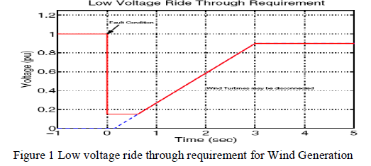
| To perform satisfactorily during the voltage dip, a wind generator should follow the characteristic shown in Figure 1, also known as E.ON. Netz LVRT characteristic [4]. The wind turbine generator should remain connected for all normally cleared faults and support the system [2]. The generator may be disconnected once the grid voltage goes below the curve (in time duration or voltage level). The wind generator should provide active power in proportion to retain voltage and deliver maximum reactive power during voltage dip. |
 |
MACHINE DESCRIPTION |
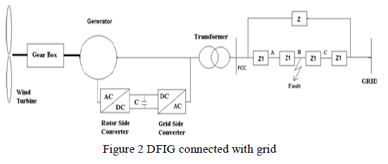
| Both stator and rotor side of a DFIG would generate the electrical energy if it is driven at a speed greater than its synchronous speed. However; the rotor would absorb the reactive power from the system if the speed is lesser than its synchronous speed. The generated voltage frequency is directly proportional to the difference in two frequencies, known as slip frequency [5]. The slip frequency is transformed to grid frequency before the generated power is taken to the grid. The stator is normally connected directly with the supply grid. The rotor is then supplied via a frequency converter as shown in Figure 2. |
 |
MATHEMATICAL MODEL |
| The equivalent circuit of a DFIG in an arbitrary reference frame rotating at synchronous speed is shown in Figure 3 [7]. |
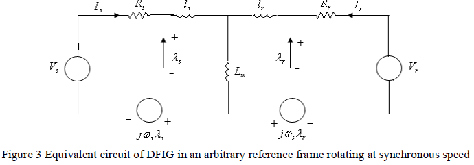 |
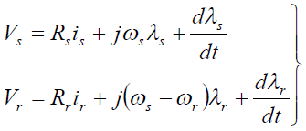
| According to the Figure 3, the stator and rotor voltages are represented by equation (1). |
 |
| If stator voltageVs and λs are assumed to be constant, the above set of equations for stator and rotor voltages in d - q coordinates can be written as shown in equation (2). |
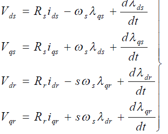 |
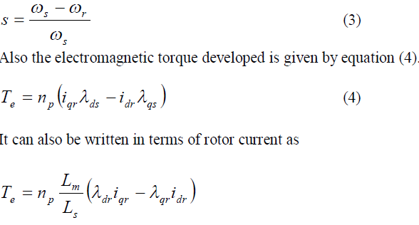
| The subscripts d and q indicate the direct and quadrature axis components of the reference frame, where s and r represent stator and rotor quantities, respectively. The decomposition into d - q coordinate systems is required for the control. |
| The rotor slip is defined by equation (3). |
 |
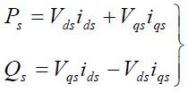
| The equations for active and reactive power in d and q axes are expressed by equation (5). |
 |
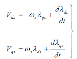
| Normally a medium to high power generator is used in wind farms; therefore the stator resistances can be neglected. The stator voltage along d - q axis from equations (2) will reduce to equation (6). |
 |
| In vector control method, which is used to achieve independent control of active and reactive power, the stator flux vector is aligned with d -axis which gives the following equations. |
| The electromagnetic torque, stator active power and reactive power can be derived as: |
 |
| From equations (07) & (08), it can be concluded that the delivered power depends directly on the d and q components of rotor currents except that for the reactive power there is second term, which represents power needed to magnetize the machine. |
| When a voltage dip occurs, the stator flux can not follow the sudden change in stator voltage, and a DC component in the stator flux appears because the integral term is reduced and the stator flux vector becomes almost stationary[6]. The rotor keeps turning and high slip is generated, which tends to introduce over-voltage and over-current in the rotor circuit due to the effect of speed voltage. The dip in the grid voltage will also result in an increase in the current in the stator windings of the DFIG. Because of the magnetic coupling between stator and rotor, this current will also flow in the rotor circuit and the power-electronic converter [8]. |
SIMULATION RESULTS |
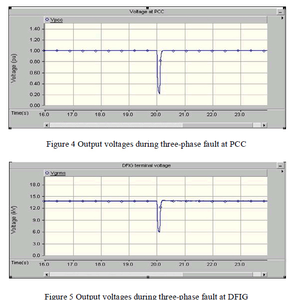
| The DFIG is connected to a network consisting of two parallel paths Z and Z1 as shown in Figure 2. A step-up transformer is used in between the grid and the generator. The wind velocity during the simulation is assumed to be constant. A three-phase fault is simulated at mid point ‘B’ of one of the two parallel lines. The fault is initiated at 20 sec and is cleared after 0.1 sec. It can be noticed in Figure 4 & 5 that the voltage at the PCC and DFIG generator falls during the disturbance. |
 |
DISTRIBUTION STATIC COMPENSATOR (D-STATCOM) |
| A wide range of Flexible AC Transmission Systems (FACTS) technology is finding several applications in modern power system networks. FACTS use an inverter to couple a capacitor or other energy storage device to the grid and provide control of VARs. Power System CAD (PSCAD)/EMTDC is chosen as the simulation platform for carrying-out design of power electronics interfaces associated with the generator module. |
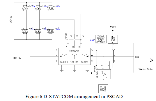
| In this paper a D-STATCOM has been tried out. The schematic diagram of this device is shown in Figure 6. It consists of a VSC, a DC energy storage device, a coupling transformer and associated control circuits. The coupling transformer is connected in shunt with the wind turbine. This type of controller can be placed individually for each wind generator or a single one of high capacity may be installed at the point of connection of wind generators |
 |
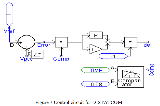
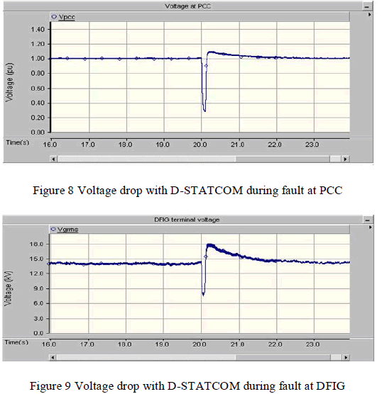
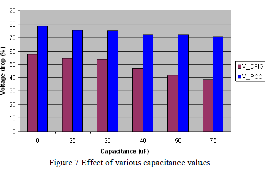
| A three-phase fault is initiated at point ‘B’ (Figure 2) at 20s for a period of 0.1s and simulations are carried out for voltage profiles at DFIG output and at PCC with and without D-STATCOM arrangements (Figure 7). The simulation results of the voltage drop with D-STATCOM during fault at PCC (Point of Common Coupling) & DFIG are shown in Figure 8 & 9. |
 |
| Simulation results clearly show that the voltage dip is less with D-STATCOM wherein the voltage dip is more for the same nature of fault when simulated without STATCOM. The reduced voltage drop at PCC and DFIG with this scheme improves the voltage profile and can be used for LVRT purpose in wind farms. |
 |
| Simulations are further carried out to investigate the effects of different sizes of the capacitance on the performance of D-STATCOM. When the value of the capacitance is increased, it is observed that the voltage dip during the fault is reduced but with an increase in initial post-fault transient recovery voltage. The effects of various capacitance values of D-STATCOM in voltage drop at PCC and DFIG terminal are as shown in Figure 7. |
 |
| It is observed that proper adjustment of the phase and magnitude of D-STATCOM offers effective power control between AC system and controller. Table 1 shows the comparison for the voltage profile with and without DSTATCOM |
 |
CONCLUSION |
| It can be concluded from the simulation results that stability can be greatly enhanced if provision is made for some level of dynamic compensation in the form of D-STATCOM. It is found that the voltage dip during the fault is reduced at the PCC as well as at the DFIG terminal, thereby improving LVRT. At the same time, post-fault rise in recovery voltage is also observed, which needs to be taken into account while choosing the capacitance value of D-STATCOM. The coupling transformer rating must also be chosen in accordance with the rating of DFIG and grid fault level at the PCC. The effects of change in value of the D-STATCOM capacitor are also analysed. This type of controller can be placed individually for each wind generator or a single one of high capacity may be installed at the point of connection of wind generator. Thus STATCOM is suitable for power system operation in normal and fault conditions. |
References |
|