ISSN ONLINE(2319-8753)PRINT(2347-6710)
ISSN ONLINE(2319-8753)PRINT(2347-6710)
Arya B. Changela 1, Dr. Ramdevsinh Jhala 2, Chirag P. Kalariya 3 Keyur P. Hirpara 4
|
| Related article at Pubmed, Scholar Google |
Visit for more related articles at International Journal of Innovative Research in Science, Engineering and Technology
In the world of robotics, the parallel kinematic manipulators have proved their unique potentials like rigid structural capacities, better dynamic behaviours, and excellent spatial positional accuracy for many applications. One of the prime focus areas of the paper is to test and to establish a simplified novel approach for the Inverse Kinematics problem solution for a 3-PSU Parallel Kinematic Manipulator platform. Additionally, the methodology for simulation of Inverse Kinematics has been checked and verified. The obtained solution is further used for positional simulation of virtual prototype of 3-PSU PKM using Pro/Mechanism module. Further, these derived data is used for simulation of the Rigid Dynamics Solution for PKM (considering inertial forces acting on actuator) is also simulated in case of circular contouring.
Keywords |
| Parallel Kinematic Manipulator, PKM, Parallel Manipulator, Inverse Kinematics, Rigid Dynamics, Simulation. |
INTRODUCTION |
| The Parallel Kinematic Manipulator has gained a lot of attention to researchers and academicians from research, academics and industrial organizations just because of the reason behind this, that is their high dynamic characteristics, rigid structures, non-additive error propagation and high positional accuracies of the parallel kinematic manipulator (PKM) [1]. The closed loop connections of linkages establish a rigid structure of PKM. The payload to self weight ratio is also enhanced because of multiple linkages support the moving link, which further results into good dynamic characteristics. The PKMs generally have different theoretically possible configurations of joints and actuators [2], notations, different kinematic and dynamic characteristics, control schemes and workspaces [3]. The first aim of this paper focuses on to study and to verify a novel, simplified geometrical approach to solve inverse kinematic solution of 3-PSU PKM configurations using advanced CAD software and Simulation software like Pro/E mechanism and MATLAB. The second aim is to study a simulation methodology for Rigid Dynamics solution for same setup for a specific toolpath (i.e. circular contouring) at lower speeds in order to check if considerable amount of forces act on actuators while motion due to inertial forces developed at joints or not. The obtained results will be checked with reference to the odel and result profile as suggested by Saha and Rao [4]. As the wide variations in PKMs are possible as far as the configuration of the setup is concerned, firstly the notation scheme and Degree of Freedom must be discussed to decide the methodology for solution. These discussions are carried out in next sections. |
II. METHODS, NOTATIONS SCHEME AND DEGREE OF FREEDOM |
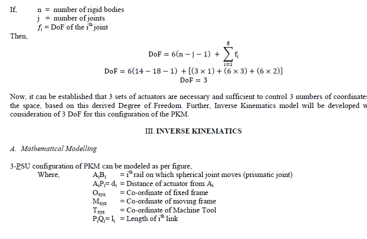
| In literature, uniform notation scheme of mechanical link arrangement of PKM has not been defined adequately. Because of lack in standard scheme, no sophisticated software has been designed with proper modular library facility. Although, the configuration (also known as 3-PSU configuration) of Parallel Manipulator can be elaborated as following; ‘3’ denotes three Degree of Freedom (DoF), ‘P’ stands for actuated prismatic joint, ‘S’ refers to ball & socket (spherical) joint & ‘U’ means Universal joint. Three serial P-S-U links are connected in parallel manner in spatial space. [5]. These three translatory motions are considered along mutually orthogonal axes, and three rotary motions around these axes. Degree of Freedom (DoF) does not answer the question if the PKM is Planar or Spatial. The total numbers of variable required for actuator parameter (either prismatic or rotary) can be related with total DoF. For example, DoF of manipulator of Stewart platform is six, means all three rotational and all three translatory motions are available with this PKM. The PKM has been suggested with 3-DoF (actuated by three stepper motors) though, it is an example of planar robot manipulator [6]. Depending upon the DoF the range of applications of application ranging from spatial applications like pick and place, material handling, MEMS, medical application, wire robots, CMM, astronomy, vibrations, sun-tracking, biomechanics, simulators, machine tools [7] to Planar applications [8]. |
 |
 |
 |
 |
 |
IV. RESULT |
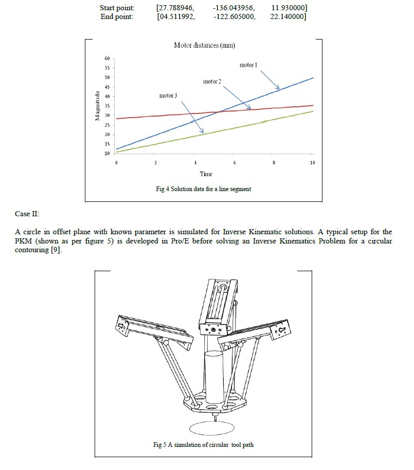
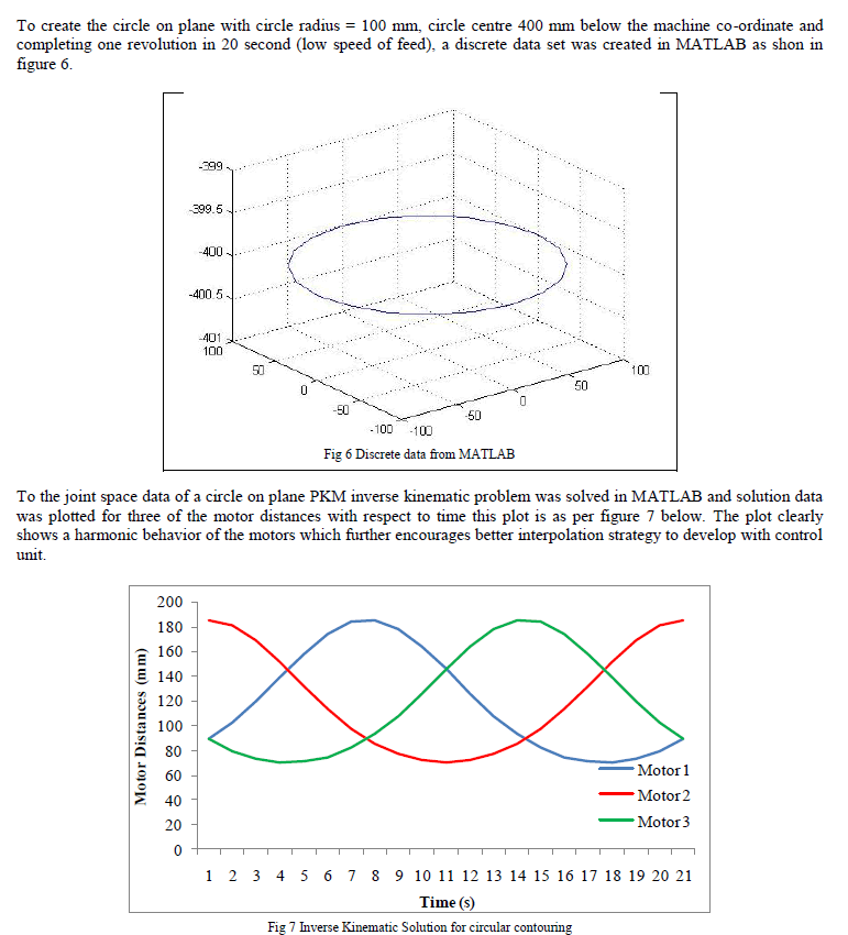
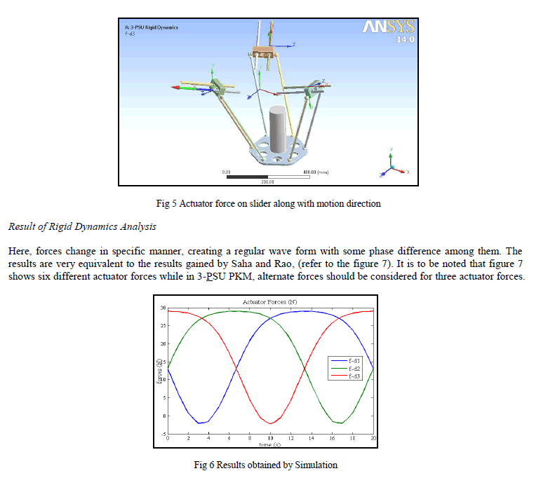
| Dynamic Analysis of the 3-PSU PKM, with the model setup discussed in previous section measures for the reaction forces acting on three different actuated moving parts. The force, F-d3 shown in figure 5 measures the reaction force on moving actuator due to the inertia of all moving parts. Similarly all the three forces along with its motion direction are measured separately during the single revolution of tool-platform on circular contouring of 100 mm radius. As the result of the Rigid Dynamics analysis of the current case, the forces were found as shown in figure 6. |
 |
V. CONCLUSION |
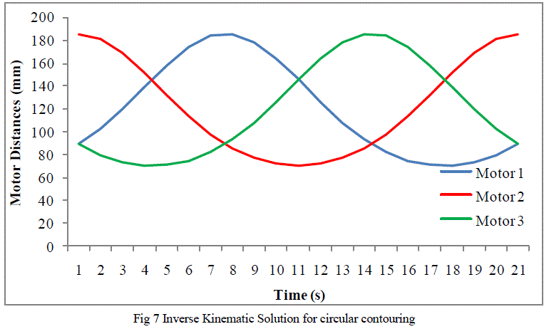
| For a line segment and a circular path inside workspace, first Inverse Kinematic solution has been done with the use of MATLAB and further the solution has been verified with Pro/E mechanisms. Thus, a simulation methodology has been checked for a sample virtual prototype. Further, dynamic analysis of the structure for a sample case has been done with the use of Rigid Dynamics (Ansys). The nature of the results is analyzed and compared with the results obtained by Saha and Rao who have worked on DeNOC methodology. |
 |
| It is to be concluded that, inertial forces produced by the motion of moving components of 3-PSU PKM at lower speeds are needed to be considered. The concept significantly suggests that these forces cannot be neglected while designing actuator components and while designing control scheme for actuation. |
References |
|