ISSN ONLINE(2319-8753)PRINT(2347-6710)
ISSN ONLINE(2319-8753)PRINT(2347-6710)
Atayeb Omer Shuaib1, Muawia Mohamed Ahmed 2
|
| Related article at Pubmed, Scholar Google |
Visit for more related articles at International Journal of Innovative Research in Science, Engineering and Technology
One of the most important issues in control system design is to ensure the stability of the plant. PID controller used in industrial solutions still represents the most common controller in industry. However PID can only guess stability area and indicates stability zone by trial and error together with the experience of the designer. Decrement of system performance index leads to easier and better control system stability. Integral time absolute error (ITAE) is one of the most criterion used to reduce system error and give the best PID gain values for a desired system response requirements. This paper discusses the steps used to obtain a proper PID gain parameters values using ITAE method.
Keywords |
| Robust control, Integral Time Error, PID controller, Step response. |
I. INTRODUCTION |
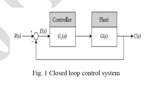
| In modern control theory its assume that required system performance can easily be specified properly, where the performance index is calculated and measured or used to obtain the whole system behaviour quantitatively [1]. We consider control system with feedback shown in Fig (1) bellow where the close loop transfer function is: |
 |
 |
| The selection of PID controllers is basically a search problem in a three dimensional space, and by choosing different points of parameter space we can produce different step response for a step input. PID controller can be determined by moving this search point by trial and error basis[2]. |
| The main problem in the selection of PID coefficients is that they do not meet the desired performance index or robust control system that the designer requires, in this section we will produce one of several robust PID controller design method which are[3]: |
• Integral Squire Error (ISE): |
| It integrates squire error over time and penalizes large errors more than smaller ones. Control systems specified to minimize ISE will tend to eliminate large error quickly, for that it presents fast response but with low amplitude and oscillation, the ISE defined as: |
 |
| where t is the time and e(t) is the difference between set point and controlled variable. |
• Integral Absolute Error (IAE): |
| Integrates the absolute error over time, and it does not add Weight to any of the errors in the system response, it tends to produce slower response than ISE but with less sustained oscillation, described as: |
 |
II. INTEGRAL TIME ABSOLUTE ERROR (ITAE) METHOD |
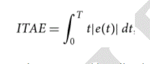
| Integrates the absolute error multiplied by time over time, it weights errors which exist after a long time much more heavily than those at start of the response, its relationship is[4]: |
 |
 |
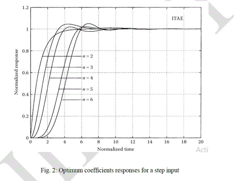 |
| The transfer function T(s) has to normalized when determining the optimum coefficients.. For the transfer function of a third order: |
 |
| Equation (7) is the normalized third order transfer function, the same procedures are followed to obtain the higher order. |
III. ROBUST PID CONTROLLED SYSTEM OF A DC MOTOR |
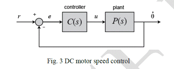
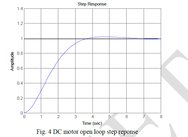
| Consider a DC motor with a transfer function as in equation (8) and block diagram as shown in figure (5) bellow, its assume that the input of the system is the voltage source (V) applied to the motor's armature, where the output is the rotational speed of the shaft dθ/dt [5]. The rotor and shaft are assumed to be static. We also assume a viscous friction model, that is, the friction torque is proportional to shaft angular velocity as in the following[6] [7]: |
 |
 |
 |
 |
 |
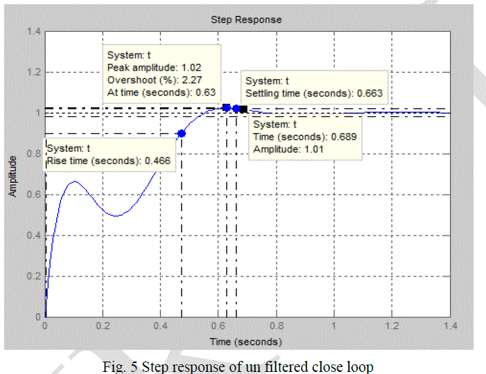 |
| in oerder to eleminate the zeros in equation (7) and bring overall numerator to 1000, we require |
 |
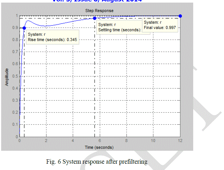
| With step response as shown in Fig. 6 bellow. |
 |
VI.RESULTS DISCUSSION |
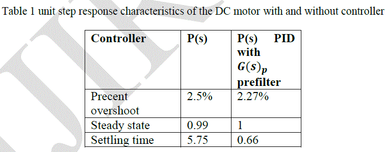
| Control system design using ITAE gives predictable response and indicates clear system behaviar, specially in determining the desired settling time. Beside that ITAE guesses optimum PID gain value and desiralbe time respone paramters. Table(2) bellow shows DC motor response parameters with and without PID with prefilter gain. The table shows clearley the benefits of using the ITAE with a prefilter controller to achieve the desired response values. |
 |
V. CONCLUSION |
| In control system design the controler is necessary to obtain the desired performance. The PID controller was used in this paper to obtain the design criteria. ITAE peformance index was used to determine the values of Kp, Kd, and Ki of the PID controller. Results have shown that the ITAE method is an optimum in finding the appropriate robust PID parameters. |
References |
|