ISSN ONLINE(2278-8875) PRINT (2320-3765)
ISSN ONLINE(2278-8875) PRINT (2320-3765)
A.Tejeswar reddy1, P.K.Senthil kumar2
|
| Related article at Pubmed, Scholar Google |
Visit for more related articles at International Journal of Advanced Research in Electrical, Electronics and Instrumentation Engineering
This paper explains the feed forward control of furnace using DCS (distributed control system). The outlet temperature of the crude oil from the coil is maintained at desired temperature before passing crude oil into distillation column, as we are using feed forward control, disturbances are measured earlier and according to that the firing section is controlled, as a result utilization of fuel will be maximum and desired temperature is maintained. So for that we have designed control algorithm in yokogawa cs2000 DCS software
Keywords |
| Furnace, DCS, yokogawa cs2000,Feed forward control |
INTRODUCTION |
| A furnace is a device used for heating. Also, the term furnace on its own is generally used to describe household heating systems based on a central furnace (known either as a boiler or a heater), and sometimes as a synonym for kiln, a device used to fire clay to produce ceramics. The term furnace can also refer to a direct fired heater, used in boiler applications in chemical industries or for providing heat to chemical reactions for processes like cracking. In so many industries furnace is controlled by using feedback method, as it is controlled by feedback manner, it has some disadvantages like the feedback circuit wont detect the change in input side, which means it cant measure disturbances. The desired set point varies depending up on the crude type and the distillation column condition and priority of products. The temperature control is achieved by means of controlling flow, pressure and level. We have studied the system and found that the following parameters are affecting the outlet temperature of the furnace which are |
| • Moisture |
| • Atmospheric changes |
| • Feed flow |
| • Fuel flow |
| So our objective is to design the control algorithm which should take care of any changes in the above process parameters. To solve the given problem we came out with a hybrid controller module, so in order to avoid the disadvantage we designed feed forward method to avoid disturbance. |
LITERATURE SURVEY |
| 1. “Improving of refinery furnaces efficiency using mathematical modelling”,international journal of modelling and Optimization. |
| 2. “Mathematical modelling of coal fired furnace”,Monografias de la real academia. |
| 3. “MATLAB modelling of arc furnace for flicker study”,IEEE Xplore. |
| 4. Alireza bahadori,hari B.Vuthaluru. “Novel predictive for design of radiant and convection sections of direct fired heaters”, Apllied Energy, Vol.87, pp.2194-2202, 2009. |
PROPOSED METHODOLOGY |
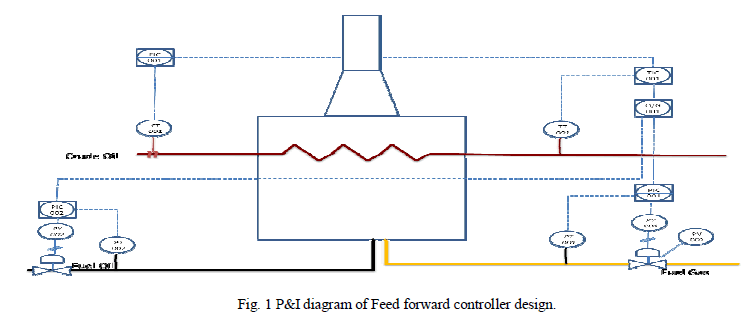
| The traditional feedback controller which was in use reacts only after it has detected a deviation in the value of the output from the desired set point .The advantage to a feed-forward control strategy is that a disturbance variable is measured and a manipulated variable is changed before the output is affected. In the proposed hybrid controller the feed forward controller compensates for any deviation in the feed flow rate in all the four coils. |
| In fig.1 basic design is shown where the crude oil is pumped from the storage tanks, so during pumping if there is any disturbance at input side or any disturbance due to atmospheric changes, the flow transmitter(FT) transmits data to flow indicator and controller (FIC) will detect and send the signal to temperature indicator and controller (TIC), so the TIC unit will compare the present value and set point value and then according to that the selector switch will select the amount of fuel oil and fuel gas. The pressure indicator and controller (PIC) will receive signal from o/g selector switch, according to that the control valves of fuel oil and fuel gas are controlled. The pressure converter (PY) converts the current signal to pressure signal using I to P convertor. |
 |
PASS BALANCER DESIGN |
| Generally in so many industries furnace section contains only one coil to pass crude oil to maintain at desired temperature, but in some industries where production is high requires more number of coils to pass crude oil. Pass balancer calculates the amount of crude oil to flow through each coil and even manually also we can set the desired rate. |
| The furnace pass balancer package calculates the ratio parameters, for each individual furnace pass flow controller, required to achieve equal flow pass through all coils. |
| The below equation calculates the furnace weighted average outlet temperature. |
| TWA = (Fi * Tout,i)/Fi |
| TWA= furnace weighted average outlet temperature |
| (Fi * Tout,i)= the sum of the products of each pass flow setpoint times its outlet temperature |
| Fi = the sum of all pass flow sepoints |
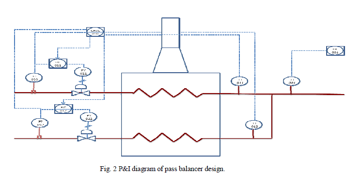 |
| In fig. 2 pass balancer design is shown, initially flow transmitters (FT) sense the flow thorough coils and sends signal to FIC units and also to calculator section, so as per the change in flow rate desired set point is maintained. A balanced furnace is defined as having equal outlet temperature for all passes. |
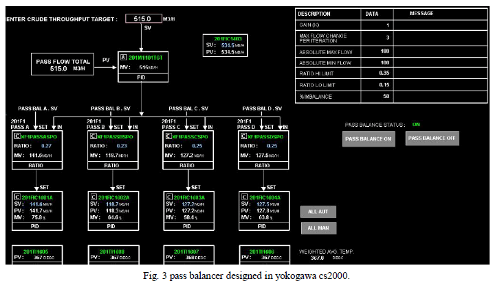 |
| Pass balancer design is shown in fig .3 ,in this example as we are using four coils in furnace to pass crude oil, for that reason we are using four blocks to enter set point range, by setting the ratio desired will pass though each coil. Pass balancer can work in auto or manual mode. For each of the blocks and control valves some tag name is given for representation. Suppose if same tag name is used in different place like in field and control room they will active at the same time. PID controllers are used to control the flow for proper control action. |
FURNACE SECTION |
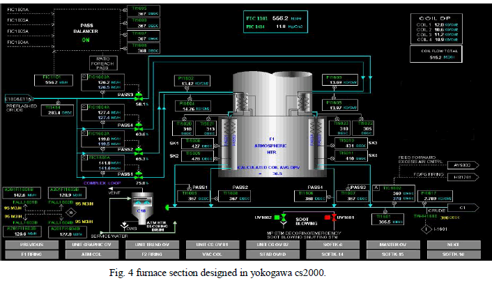 |
| In this furnace section coils are arranged, so that crude oil will get heated to desired set point. In this coils are arranged in zigzag manner because crude oil will get heated at multiple points. |
| In fig .4 initially crude oil will enter and then flow rate is measured by FIC unit and then given to pass balancer circuit, so the pass balancer circuit will decide the amount of flow through each coil, as the pass balancer is directly connected to the temperature transmitters, it will inform immediately about the flow rate and disturbances at the input side, so that it acts as feed forward controller in the circuit. |
| In the furnace section at multiple points temperature is measured, at the end of the coil temperature information is given to TIC unit which will compare to the set point, suppose if the temperature is less than desired, selector switch will pass the fuel oil and fuel gas as per required temperature. The tag name HS1701 is given to firing section which will act immediately if there is any change in temperature. |
| In furnace section interlocks are designed by using programmable logic controller (PLC) for safety purpose, suppose if there is any drastic change (too high or too low) in flow rate then interlock can shut down the system. |
SOOTBLOWER |
| Sootblowers utilize flowing media such as water, air or steam to remove deposits from boiler tubes. There are several different types of sootblowers used. Wall blowers are used for furnace walls and have a very short lance with a nozzle at the tip. The lance has holes drilled into it at intervals so that when it is turned on, it rotates and cleans the deposits from the wall in a circular pattern. After it has turned a predetermined number of rounds, the sootblowing is completed and stops. Below is a convection section sootblower utilizing medium pressure (10-12bar). |
FIRING SECTION |
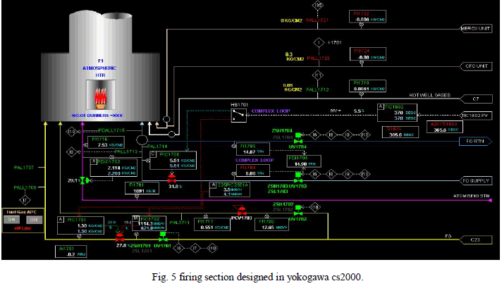 |
| In firing section shown in fig.5, where fuel oil and fuel gas are supplied which are controlled by selector switch HS1701.generally steam is also supplied simultaneously for proper burning inside the furnace. Number of burners can vary as per requirement, burners can also arrange vertically or horizontally, if burners are arranged in horizontally firing pattern is easy to control when compare to vertical manner. Pressure differentiator and indicator (PDIC) is arranged between fuel oil and steam in order to supply proportion rate. |
| All control valves are linked up with interlock system to avoid any misshapen during emergency, for suppose if there is any misfire in furnace section then interlock will get active and close all the valves which are passing into firing section. |
| In above figures each and every sensor and control valves are given with particular tag names, so that the same tag name can be used in plant. TIC1602 is the tag name of final outlet temperature indicator and controller of the main coil, this TIC1602 is given to oil/gas selector switch which will allow fuel oil and fuel gas proportionally as per required for all the burners in the firing section. |
CONCLUSION |
| The temperature control is thus achieved by means of controlling flow and pressure. We have studied the system and found that the following parameters are affecting the outlet temperature of the furnace. |
| • Moisture |
| • Atmospheric changes |
| • Feed flow |
| • Fuel flow |
| To solve the problem we came out with a hybrid controller module which comprises ofFeed forward controller. The accuracy of the existing system is 0.05%.By employing the designed system the outlet temperature of the furnace is maintained with an accuracy of 0.02%. |
References |
|