ISSN ONLINE(2319-8753)PRINT(2347-6710)
ISSN ONLINE(2319-8753)PRINT(2347-6710)
S. Kanagamalliga1, Dr. S. Vasuki2, A. Vishnu Priya3,V. Viji4
|
| Related article at Pubmed, Scholar Google |
Visit for more related articles at International Journal of Innovative Research in Science, Engineering and Technology
The Security monitoring systems today needs to make use of the latest technological components available. In this paper, we present the design and implementation of a security monitoring system based on embedded and zigbee. In this paper there is a centralized control system that is utilized for the purpose of controlling the operations of various devices and equipment. The system presented in this paper is a combination of Zigbee and GSM. PIR, vibration and magnetic contact sensors are installed at windows and doors along with zigbee end devices. Whenever there is an intrusion, respective sensor sends a signal to the ZC using Zigbee communication protocol. The ZC at the control console communicates with MCU using its builtin UART. MCU would in turn access and control the GSM module via AT commands and automatically sends SMS to the owner's mobile phone informing him about the security breach. When the user is at his own premises then traditional alarm mode is used to ensure reliability. When the user is at remote premises, SMS indicating theft has occurred is sent to the owner. Then Smart phones installed with app „free Internet web cam‟ are used as a security camera for monitoring the home. On receiving the SMS, user can make a video call, Smartphone camera will feed us with a live video. On viewing the video the owner can know whether an intruder has entered or not. Then accordingly faint gas valve can be controlled by the owner. In addition the user can also control the door lock.The system is intelligent enough to monitor the secure environment and let the user know about the security breach. Thus the remote user can control his premises from any part of the world.
INDEX TERMS |
| ZC (Zigbee Coordinator),MCU(Micro Controller), GSM, Sensors. |
INTRODUCTION |
| One of the most effective modern technologies for home safety is a security system. These systems monitor the most critical areas of the house in order to detect intrusions or other anomalies that might otherwise go unnoticed. During recent past, a number of systems were introduced for security measurements based on wired networks. In literature, researchers suggested a number of security systems based on new technologies like GSM (Global System for Mobile communication), USN (ubiquitous sensors network) and implemented through FPGA (field programmable gate arrays), DSP (digital signal processor), and MCU (microcontroller unit). A Java based home automation system is developed. An embedded board physically connected all the home automation devices and, through integration with a personal computer (PC) based web server, provided remote access to the system. The use of Java technology, which incorporates built-in network security features, produces a secure solution. However, the system requires an intrusive and expensive wired installation and the use of a high end PC [1]. Introduced a Bluetooth based home automation system, consisting of a primary controller and a number of Bluetooth sub-controllers. Each home device is physically connected to a local Bluetooth subcontroller. The home devices communicate with their respective sub-controller using wired communications. From the sub-controller all communications are sent to the primary controller using wireless communications. It is desirable for each home device to have a dedicated Bluetooth module. However, due to the fiscal expense of Bluetooth technology, a single module is shared amongst several devices. This architecture reduces the amount of physical wiring required and hence the intrusiveness of the installation, through the use of wireless technology. However, the architecture does not completely alleviate the intrusiveness of the installation due to the incorporation of some wired communications. Moreover the sharing of a single Bluetooth module between numerous devices has the disadvantage of incurring an access delay [2].Home automation system using GSM, Internet and speech recognition. In this system the home gateway is internet which require personal computer (PC). However, it's hard to manage PC and keep it ON all the time. Also it consumes more power [3]. The architecture and simulation of a GSM based remote sensing and control system using FPGA is discussed [7]. Authors proposed a zigbee based home network configuration. This system controls all home appliances through zigbeeinfrared combination and zigbee power adapter [8]. An internet-based intelligent system for home power management aiming to reduce energy consumption is explained. This system also uses internet cloud as a home gateway having the same limitations as described earlier [10]. |
II. PROPOSEDSYSTEM |
| The project can be served into two parts: the hardware part and the software part. While the former is all about incorporating MCU with sensors, ZigBee architecture, and mobile phone to build a working circuit that supports portability without compromising reliability, the latter is to make an ingenious C-code for programming the MCU and ZigBee module to monitor and control secured environment. |
| A. Hardware |
| Hardware of the system is comprised of ZigBee EM357module, Pic micro controller, GSM module,a smart phone with net connectivity and corresponding interfaces.Zigbee is a technological standard for control and sensor networks. It is created by zigbee alliance and is based on the IEEE 802.15.4 standard. It operates in two separate frequency ranges namely 868/915 MHz and 2.4 GHz and uses digital radios to allow devices to communicate. Though low-powered, these devices can transmit data over long distances by passing data through intermediate devices to reach more distant ones, creating a mesh network; i.e., a network with no centralized control or high-power transmitter/receiver able to reach all of the networked devices. The decentralized nature of such wireless ad hoc networks makes them suitable for applications where a central node can't be relied upon. ZigBee is used in applications that require only a low data rate, long battery life, and secure networking. ZigBee has a defined rate of 250 kbit/s, best suited for periodic or intermittent data or a single signal transmission from a sensor or input device. TheZigBee network is a PAN (personal area network) network, comprises of one ZC (ZigBee coordinator) and one or more ZEDs (ZigBeeend device). ComparingZigBee with Bluetooth, the ZigBee has significance in building control wireless sensor networks.The Zigbee module can be installed with any sensor and home appliances as it is very small in size i.e. 21mm x 37mm, and a low power consuming device. |
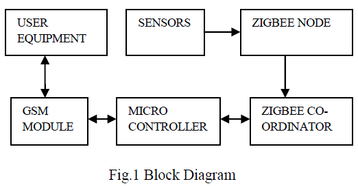 |
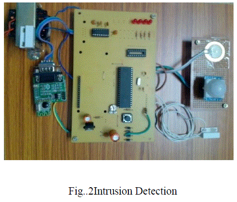
| In the design three sensors namely PIR sensor, vibration sensor and magnetic door contact sensor are used. Vibration sensor and magnetic door contact sensor are installed at the window and door. Vibration sensor is used for detecting window breaking; magnetic door contact sensor is used for sensing door opening and PIR sensor is used for detecting human presence. ZED is connected with door contact sensor, PIR sensor, and door lock system respectively. ZigBee node continuously checks input from the corresponding sensor and sends a wireless message to the Zc. |
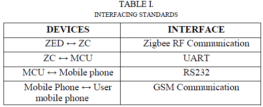
| The control console consists of Pic micro controller and ZC EM357 module that are mountedon same PCB in our design. ZC is interfaced with MCU using built-in UART of MCU, thus giving information to MCUabout sensors status. Also ZC takes instructions from MCUfor actuators using the same interface. MCU is heart of thesystem. On one hand it is interfaced with ZC while on theother hand it is communicating with the GSM module. Moreover, the external MCU may be merged with the ARM processor inside EM357 node making the system more compact. Mobile phone can be accessed through its ports using corresponding serial cable. There occurs a serial communication between MCU and mobile phone. To allow compatibility of data communication between MCU and mobile phone, an interfacing standard RS-232 was employed. And for this purpose MAX-232 level converter IC is used. Finally, the GSM module is wirelessly connected with the user mobile phone through GSM network. |
| B. Software |
| The ZigBee module CC2520 is supported by insight desktop a comprehensive integrated developmentenvironment (IDE) and C-Language compiler tool-chain. Now to connect this chip with the sensors and MCU, its built-in UART is deployed. The Zigbee module CC2520 control all the interfaces and uses RF antenna at the end for communication purpose. The microprocessor is programmed via an ISP header on board to program flash memory of the chip. On the other hand Pic microcontroller is a general purpose MCU with a rich set of built-in peripherals. The MCU also features a built-in Flash and EEPROM memories. The flash is used to store code that is also programmed via the ISP header on theboard. For the proposed system, the MCU on one hand deals with the ZC to receive intrusion detection from the sensors installed while on the other hand it deals with the GSM module to send Short Message Service (SMS) or to call the owner. For that purpose searching through answer comes out to be the built-in UART for interfaces. Interfacing standards used in this work are summarized in Table 1. |
 |
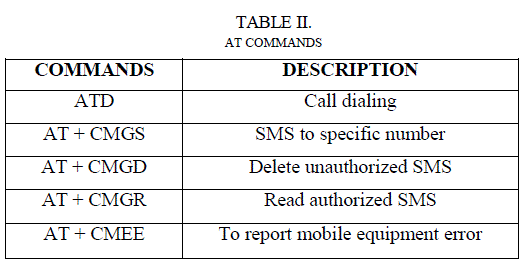
| Now that it is all set for the communication between mobile phone and the MCU, in order to control the mobile phone through its ports, we used AT Commands, provided by the vendor companies. AT commands are used to control MODEMs. AT is the abbreviation for Attention. These commands come from Hayes commands that were used by the Hayes smart modems. The Hayes commands started with AT to indicate the attention from the MODEM. The dial up and wireless MODEMs (devices that involve machine to machine communication) need AT commands to interact with a micro controller. These include the Hayes command set as a subset, along with other extended AT commands.AT commands are used to access andcontrol the built in modem of the mobile phone. Table 2 shows AT -commands that are used in the proposed system. |
 |
III.OPERATION |
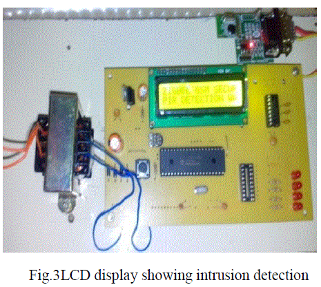
| The system presented in this paper operates in two modes, namely SMS mode and alarm mode. Desired mode can be selected with the help of mode switch. When the user is at his home, alarm mode is used in which the alarm buzzers five times for each breach in the proposed system. When the user is at remote premises the SMS mode can be used in which the user is reported about the breach through SMS. If there is any problem with the mobile phone, the system is automatically switched to the alarm to prevent malfunction. The system is designed to be user-friendly. Its installation requires sensors installation and control console installation.Sensors are installed at their respective places along with ZEDsWhenever there is an intrusion, respective sensor sends a signal to the ZC using ZigBee communication protocol. The ZC at the control console communicates with MCU using its built-in UART. MCU would in tum access and control the GSM module via AT commands and automatically sends SMS to the owner's mobile phone informing him about the security breach. Once the SMS is received the user can make a video call to the Smart phones installed with app „free Internet web camâÃâ¬ÃŸ. It feed us with live video through which we can know whether the intruder is a known person or not. |
 |
| Then accordingly gas valve is controlled by the user. If there is a reply SMS from the user, the GSM module communicates with MCU in the same manner, but in reverse direction. The mobile phone number is first scanned, if it is authorized, MCU sends a message to the ZC which in turn sends information wirelessly to the gas valve with help of the socket through ZED. |
 |
IV. CONCLUSION |
| Our project has reviewed the existing state of Security monitoring systems, and identified and discussed five areas that have hindered consumer adoption of such technologies. Briefly, the areas include: the complexity and expense of the architectures adopted by existing systems, the intrusiveness of the system installations, the lack of interoperability between different home automation technologies, and the lack of interoperability between systems developed by different manufacturers that utilize the same technology. Interface inflexibility and the inconsistent approaches adopted towards security and safety are also problems. A novel architecture for a smart security system is proposed and implemented, using the wireless communication technology ZigBee, wide covered GSM and app installed Smartphone. MCU is programmed for the system and is the heart of our project. The use of ZigBee communication technology helps lower the expense of the system and the intrusiveness of the respective system installation. The GSM communication provides worldwide coverage, easy and a low cost way of information interchange. The MCU provides interoperability of ZigBee and GSM and also makes this system portable and easy to install as the system is embedded. The system is designed to provide a secure environment by letting the user know about the security breach and who is involved in it. Not only that it also allows the user to control home appliances. Thus itenables the remote user to monitor and control his premises from any part of the world. |
References |
|