ISSN ONLINE(2278-8875) PRINT (2320-3765)
ISSN ONLINE(2278-8875) PRINT (2320-3765)
M.Wasim1, U.Sowmmiya2
|
| Related article at Pubmed, Scholar Google |
Visit for more related articles at International Journal of Advanced Research in Electrical, Electronics and Instrumentation Engineering
Wind Energy Conversion Systems are the most striking renewable energy resources available to generate the electricity. Doubly-fed Induction Generator (DFIG) based wind turbine with variable speed is the most common wind turbine in the growing wind market. In any WECS, power flow must be maintained at all instant irrespective of any fault in the system. This paper deals with fault tolerant control (FTC) of DFIG based WECS. To have a better performance fault is detected & isolated with the help of NN. This intelligent computing technique provides better close loop performance during faulty conditions. The performance of the system under various modes of operation and FDI scheme are carried out using computer simulation. The simulation tool used is MATLAB/SIMULINK.
Keywords |
| Doubly Fed Induction Generator (DFIG) Neural Network (NN), Fault Tolerant Control (FTC), Fault Detection & Isolation (FDI), Neural Observer. |
INTRODUCTION |
| Conservation of non-renewable resources motivate to explore new avenues of resources for electricity generation which could be clean, safe and most valuable to serve the society for a long period. The solution is eco-friendly renewable energy sources. These sources can be a better replacement for the polluted non-renewable sources in order to meet the growing demand for power due to rapidly growing economy and expanding population. Among various RES, wind is facing enormous merits. Variable speed WECS are becoming good source of power output when compared to other WECS. Generators used for wind energy conversion systems (WECS) are DFIG and PMSG. In this project a special type of induction generator, called a doubly fed induction generator (DFIG), is used extensively for high-power wind application is taken for study. By means of rotor current control variable speed operation can be achieved, so it can operate at maximum efficiency over a wide range of wind speeds. For variable speed operation, the standard power electronics interface consists of a rotor and stator side PWM converters that are connected back-to-back. These converters are rated, only to a fraction of the machine rated power. |
| Neural networks are a form of multiprocessor computer system, with simple processing elements, a high degree of interconnection, simple scalar messages & adaptive interaction between elements. Current sensors are connected at the stator side and fault tolerant scheme is adopted [1]. FPGA based hardware in loop validation is carried out using three phase active filters without redundant leg [5]. Feed forward neural networks new formulation is carried out using BP algorithm [4]. A multi-observer switching control strategy for robust active fault tolerant fuzzy control of variable speed operations is carried out [3]. New fuzzy scheduler fault tolerant control is proposed to tackle multi-vibrator nonlinear systems subject to sensor faults [2]. A very fault fast FPGA based fault detection scheme is presented that minimizes the number to reduced voltage sensors [8]. A residual generator based on the DFIG model is proposed using the structure of the classical generalized observer scheme, each observer in this scheme is replaced by a robust H_/H∞ fault detection filter followed by a Kalman-like observer [6]. It proposes to use of artificial neural networks to estimate one of the most important variables in the induction motor control schemes like speed [7]. |
| This paper is organised as follows. Section II explains about DFIG Sub-synchronous generating mode and Supersynchronous generating mode. Section III explains the introduction to Neural Network and presents the Neural Observers for various current and speed data’s. Section IV explains the Fault detection and Fault isolation scheme V shows the Results & Discussions. Finally, conclusions are summarized in section |
DFIG BASED WECS |
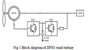
| The DFIG based WECS is shown in the fig.1. The DFIG system allows a variable speed operation over a wide range. The converter compensates the difference between the mechanical angular frequency and grid frequency by injecting a rotor current with a variable frequency. Both during normal operation and at faults, the behavior of the generator is thus governed by the power converter and its controllers. The power converter consists of two converters, the machine-side converter and grid-side converter, which are controlled independently of each other. The main idea behind the total system is that the machine-side converter controls the active and reactive power by controlling the rotor current components, while the grid-side converter controls the dc-link voltage and ensures the operation at unity power factor (i.e. zero reactive power). By means of a bi directional converter in the rotor circuit, the DFIG is able to work in both sub-synchronous and super-synchronous modes. |
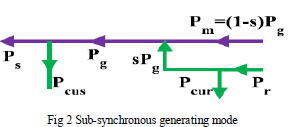
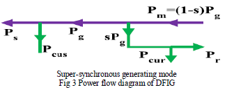
| Depending upon the operating condition of the drive, power is fed into or out of the rotor. In super synchronous mode, power flows from the rotor via the converter to the grid & as shown in fig 3In sub-synchronous mode, power flows in opposite direction as shown in fig 2In both modes the stator feeds power in to utility. |
 |
| a. Sub-synchronous generating mode |
| For, generating action of machine, Pm is negative, and the rotor speed is less than the synchronous speed (0<s<1), Pag is negative and Pag>Pm, where Pag=Pcu2+P2+Pm. Pcu2+Pm must be negative. As Pcu2 is positive, P2 should be made sufficiently negative by injecting power into the rotor circuit in order to make the rotor electrical power sPag negative. The net electrical power flowing tin the grid is, P1-P2. The directions of the various power flows for this generating mode at sub-synchronous speeds are shown in fig.2 |
 |
| b. Super-synchronous generating mode |
| For super-synchronous operation in the generating mode, the power flow diagram is shown in fig.2.2.b. s being negative (-1<s<0) in this mode, the air gap power Pag is less than the mechanical power Pm, where Pm=(1-s) Pag and is negative. The remaining surplus energy sPag is returned via the rotor circuit to the grid after providing for the secondary lossesPcu2 |
 |
NEURAL NETWORK BASED FTC SCHEME |
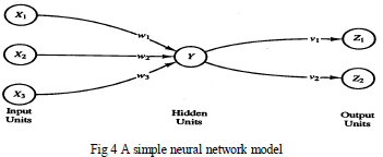
| An artificial neural network is an information-processing system that has certain performance characteristics in common with biological neural networks. A neural network is characterized by |
| 1. Its pattern of connection between the neurons (called its architecture) |
| 2. Its method of determining the weights on the connection (called its training, or learning, algorithm) and |
| 3. Its activation function (Purelin transfer function) |
| Algorithm used in this scheme trainlm which is Levenberg-Marquardt back propagation. |
 |
| In this system, speed is sensed and V/F method is used to generate the pulses for rotor side converter (RSC). Grid side converter (GSC) gains gate pulses through reference current generation technique based on p-q theory. |
| Current sensors are connected at the stator side and also the speed sensors are taken from the study. By using neural network (NN) technique, faulty sensor identification scheme has been implemented. Continuous sensing of current and speed has to be done. If any one of the sensors gets failed the faulty sensor has to be identified and that sensor should be isolated. This has to be carried out using the NN technique. This NN observer is used to identify faulty sensor. The NN observer which was trained using MATLAB/SIMULINK has been formulated for both current data and speed data. |
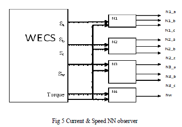
| Using current data, the Neural Network current observers, N1, N2and N3 are trained. Using the speed data NN speed observer, N4 has been trained. The NN observer connection diagram is shown in Fig 5 |
 |
| A sudden failure in the used current sensors decreases the WECS performances. Moreover, if the fault is not detected and handled quickly, its effect can lead to disconnection or hard failure of the system. These events are introduced because the current sensor outputs are used in the closed-loop control system. Hence, to reduce the failure rate and to prevent unscheduled shutdown, fault detection and compensation scheme must be adopted. The general block diagram of the FTC scheme is shown Fig 6 |
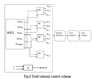 |
| As shown above, NN observers are connected with the residual calculation, in which error is calculated followed by fault detection. In this block, sensor fault is detected and it is isolated using fault isolation block. In WECS, Sena, Senb, Senc and Senw are current and speed sensors. Torque is the input; using the torque sensor values, NN observer is trained. If any one of the sensor is faulty means, for example Sena gets is faulty, N2_a (or) N3_a will act in the place of N1_a. The combination of faults taken for analysis is shown in Table 1 |
 |
| In the above tabulation, ‘F’ represents the “Fault” in the respective sensor. First four conditions are fault in the respective sensor Sa, Sb, Sc&Sω, the next three conditions are fault in both the current and the speed sensor at the same time. Similarly for all the conditions ‘F’ represents Fault and ‘0’ represents no fault. |
FAULT DETECTION AND ISOLATION |
| The proposed method is faulty sensor identification method in which totally seven conditions are employed. If anyone current sensor or speed sensor is faulty or both the current and speed sensor becomes faulty at the same time then the above conditions are used to isolate the faulty area thereby delivering uninterrupted operation. |
 |
| Condition_1 indicates that if ‘SenSa’ becomes faulty, then observer outputs N2_a or N3_a will act. Condition_2 indicates that if ‘SenSb’ becomes faulty, then observer outputs N1_b or N3_b will act. Condition_3 indicates that if ‘SenSc’ becomes faulty, then observer outputs N1_c or N2_c will act. Condition_4 indicates that if ‘SenSω’ becomes faulty, then observer outputs ωcalc will act. Similarly for other conditions at the same time both the current and speed sensor is faulty, the following conditions are, Condition_5 indicates that if ‘SenSa’ and ‘SenSω’ becomes faulty, then observer outputs N2_a or N3_a and ωcalc will act. Condition_6 indicates that if ‘SenSb’ and ‘SenSω’ becomes faulty, then observer outputs N1_b or N3_b and ωcalc will act. Condition_7 indicates that if ‘SenSc’ and ‘SenSω’ becomes faulty, then observer outputs N1_c or N2_c and ωcalc will act. |
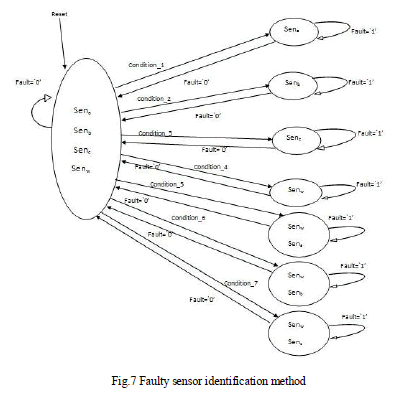 |
| Fig 7 indicates the state diagrammatic representation of faulty sensor identification method. It is the proposed model for faulty identification scheme in which if no fault occurs means all the sensors are in good condition. If fault occurs in anyone of the sensor or in both the current and speed sensors at the same time, then all the conditions are formulated accordingly. |
RESULTS AND DISCUSSIONS |
| The DFIG based WECS is initially tested under various speed conditions. |
| Sub-synchronous generating mode |
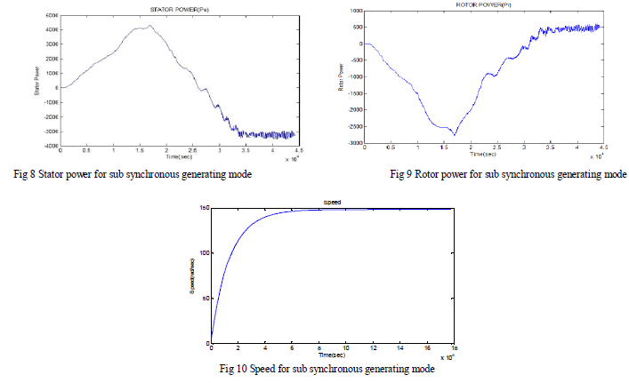
| The simulation is carried out for various speed conditions. For sub synchronous operation the machine is made to run at s speed of 1414 rpm and various oscillographic waveforms are obtained. Fig 7 shows the stator power for sub synchronous generating mode; Fig 8 shows the rotor power for sub synchronous generating mode, Fig 9 shows the speed of the sub synchronous generating mode |
 |
| . Super-synchronous generating mode |
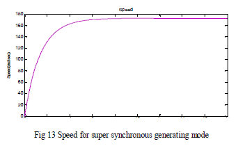
| For super synchronous operation the machine is made to run at s speed of 1605 rpm and various oscillographic waveforms are obtained. Fig 10 shows the stator power for super synchronous generating mode, Fig 11 shows the rotor power for super synchronous generating mode and Fig 12 shows the speed for super synchronous generating mode. |
 |
 |
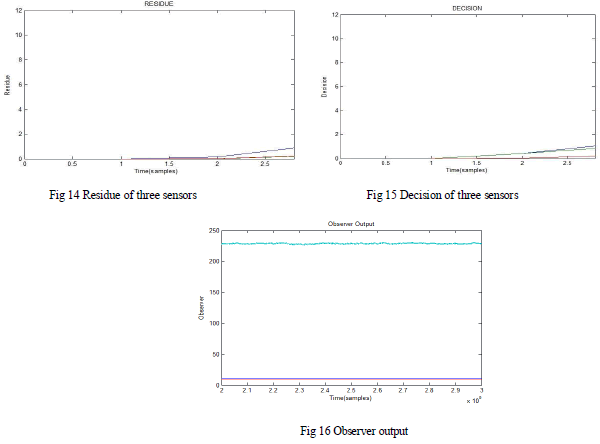
| Fig 14, 15, 16 are the residue, decision & observer output for non-faulty case |
 |
 |
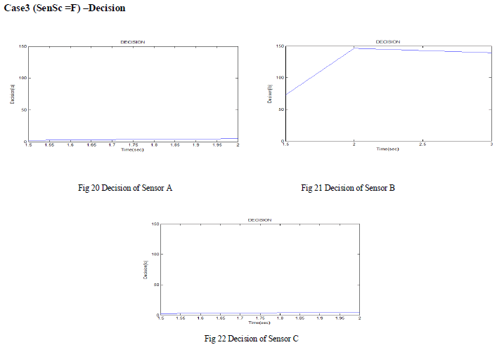 |
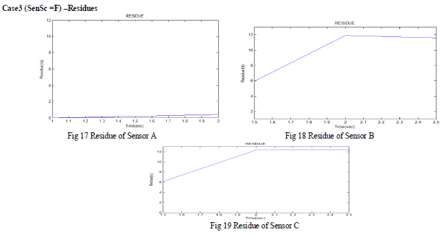
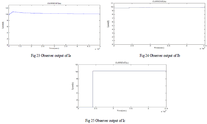
| Using the case3 the fault is introduced in sensor C at the time=2.4 (sec) and the observer output for the same. |
 |
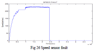
| Case4-residue, decision & observer output |
Case4-(SenSw=F) |
 |
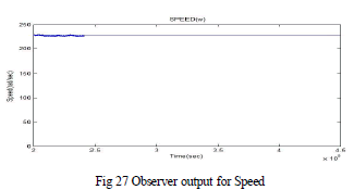
| The fault is introduced at time=2.4 (sec), the observer output for the same |
 |
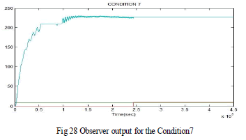
| Case7- both the Current sensor C and the Speed sensor are introduced the fault at the time=2.4 (sec) and the residue, decision & observer output |
Case7- (SenSc =F)&-(SenSw=F) |
 |
CONCLUSION |
| WECS with DFIG can operate in various modes and is gaining laurels. Sensors are involved in measuring certain parameters used in the control scheme of converters to yield better output. At abnormal conditions these sensors may become faulty leading to undesired output. NN based Fault Tolerant Control scheme is adopted. The physical model of DFIG based WECS is developed using MATLAB/SIMULINK and the same is analysed for various speed conditions and the results are validated. NN based observer is trained to incorporate FTC scheme. Fault is initially detected and then isolated with the help of observers that are trained using NN. Results shown that, with NN based FTC scheme various combination of fault at sensor end are detected & isolated within small span. |
References |
|