ISSN ONLINE(2278-8875) PRINT (2320-3765)
ISSN ONLINE(2278-8875) PRINT (2320-3765)
S. Gowtham1, R. Ramaprabha2
|
| Related article at Pubmed, Scholar Google |
Visit for more related articles at International Journal of Advanced Research in Electrical, Electronics and Instrumentation Engineering
With the increasing power demand the need for generation of useful power is important. Renewable energy generation is one efficient method for producing useful power. With proper power flow control, the efficiency of power transfer increases. This paper provides an efficient power control technique namely the active-reactive power control and dump power control along with auto master-slave control. This paper also provides more efficient control compared to the paper in reference. It can be used in isolated islands as the power line is flexible, so more number of power sources can interconnected in the system there by more power can be generated.
Keywords |
||||||||||
| Hybrid System, Dump load, Dump power, PLL, PV source, Storage battery | ||||||||||
INTRODUCTION |
||||||||||
| Natural energy based power generation systems are commonly equipped with storage batteries, to regulate output fluctuations resulting from natural energy variations. Therefore, it is necessary to prevent battery overcharging [1]. As for individual power generation system, it is considered that a closed loop wind turbine system which makes use of a proportional integral (PI) controller produces a more stable output [2], or a wind turbine system that features output stability with a combination of an electric double-layer capacitor and storage battery [3], or a photovoltaic(PV) system featuring low-cost and simple control, which is efficiently modelled and simulated [4] or a PV system which incorporates maximum power point tracking(MPPT) control that makes use of diode characteristics[5], or a PV system that features output stability with a multiple-input dc-dc converter capable of controlling the output of different power sources in combination [6], or a cascaded dc-dc converter PV system that features good efficiency along with low cost [7] is suitable for use with hybrid power generation system to stabilize power supply. In contrast, the standalone hybrid system is mainly composed of natural energy sources (i.e. wind power and solar power) and a storage battery; there is a tendency that greater the system sophistication, the more suitable the power control techniques are required to be. So with a proper power control technique the power transfer will be efficient [8]. | ||||||||||
| There aredifferent ways by which the power flow can be controlled; one best method is the active-reactive power control. The active-reactive power control uses phase locked loop (PLL) and parallel operation of inverters for controlling the active and the reactive power of the system. PLL keeps the entire system in a locked state at a single frequency there by controlling the active power of the system. So use of PLL controls the active power efficiently [9]-[11]. Parallel operation of inverters is done to control the reactive power of the system. Each inverter is assumed as a reactance and using the sending end and the receiving end power the reactive power is calculated [12]-[13]. Another power control technique called dump power control is used for preventing the battery from getting damaged due to constant charging. Normally a dump load will be used for controlling the battery charging problem, another technique is that surplus power is consumed by a hydrogen generator for a fuel battery insteadof storage battery, and when the hydrogen tank becomes full, dump load is applied [14]-[15].Use of dump load or a fuel engine generator is costly and uses a large space. For proper sizing and effective control of hybrid system [16]-[17], the power flow in the system is controlled effectively with the proposed control techniques [18]-[19]. Hence inthis paper a low cost, standalone hybrid wind-solar power generation system applying advanced power control techniques is adopted. Auto master-slave control is done to control the power flow of the system. It is the controller which controls the different sources based on the load requirement. | ||||||||||
II.SYSTEM MODEL AND DESCRIPTION |
||||||||||
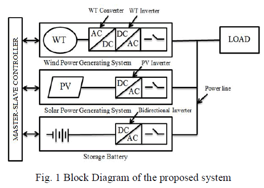
| The proposed hybrid wind-solar power generation system is, as shown in Fig. 1. The proposed system is composed of three power sources namely; a wind power generation system which is coupled to a wind turbine (WT) converter and a WT inverter, a solar power generation system which is coupled to a PV inverter, and a storage battery (with a bidirectional inverter); and a master-slave controller. The master-slave controller controls the power flow of the system. In the proposed system we can see that the battery is connected separately with the master-slave controller, this is done to avoid the battery from getting constantly charged. Normally the battery will be connected either with the wind turbine system or with the PV system and a dump load will be placed with the battery to avoid the battery from getting constantly charged. Thus the cost of the system increases, so to avoid that the battery is connected separately with the bidirectional inverter in the proposed system. | ||||||||||
 |
||||||||||
| The master-slave control for the proposed hybrid system does the following controls: | ||||||||||
| ïÃâ÷ When the power generated by solar power generating system is greater than the remaining two systems as well as the load, then it supplies the load and wind power generation system energizes the battery. | ||||||||||
| ïÃâ÷ When the power generated by wind power generating system is greater than the remaining two systems as well as the load, then it supplies the load and solar power generation system energizes the battery. | ||||||||||
| ïÃâ÷ When both solar and wind power generation systems cannot meet the load demand, then battery supplies the load with the remaining two systems energize the battery. | ||||||||||
III.POWER CONTROL TECHNIQUES |
||||||||||
| In this section, the control techniques used for the proposed work is explained. | ||||||||||
Active-Reactive Power Control |
||||||||||
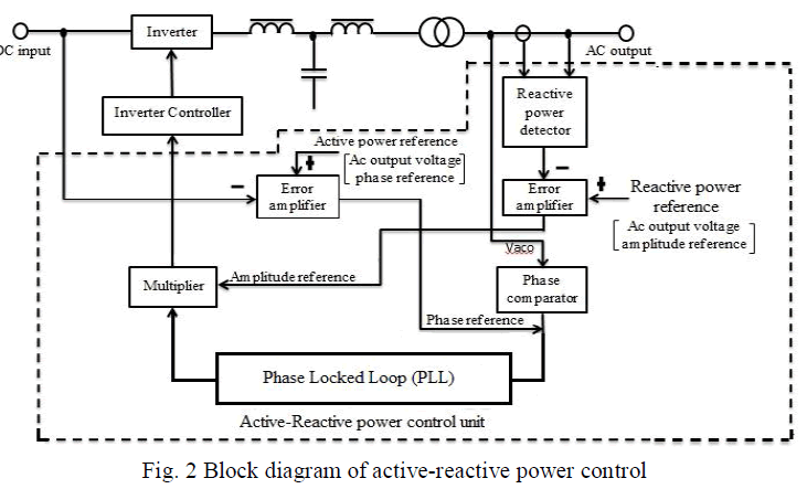
| Fig.2 shows the block diagram of active-reactive power control. This control is done for each inverter separately and is synchronized to a single frequency at the common power line. The frequency of the system is synchronized using phase locked loop (PLL). The PLL, which acts as a phase synchronization control, is composed of: a phase comparator, low-pass filter, phase shifter, multiplier, and voltage controlled oscillator (VCO). The phase comparator is the heart of the PLL, where it takes two pulse trains as the input and produces a pulse-width modulated output, the pulse-width being proportional to the difference in phase between the input trains. | ||||||||||
 |
||||||||||
| The obtained pulse width is converted to a dc value using a low-pass filter. This is then fed to VCO whose output frequency changes in response to input voltage. The low-pass filter acts as an error amplifier. By giving active power reference (i.e. ac output voltagephase reference) to the amplifier, the phase shift between sine wave reference and ac output voltage wave is adjusted while synchronization is maintained in a locked state. That is, active power control is possible by altering the dc voltage. For the reactive power, the sine wave reference regulated by VCO is multiplied with the signal in which the difference between reactive power reference and actual reactive power is amplified. The multiplied signal is defined as the control signal for inverter output voltage. By altering the reactive power reference (i.e. ac output voltage amplitude reference), reactive power control is made possible. | ||||||||||
Dump Power Control |
||||||||||
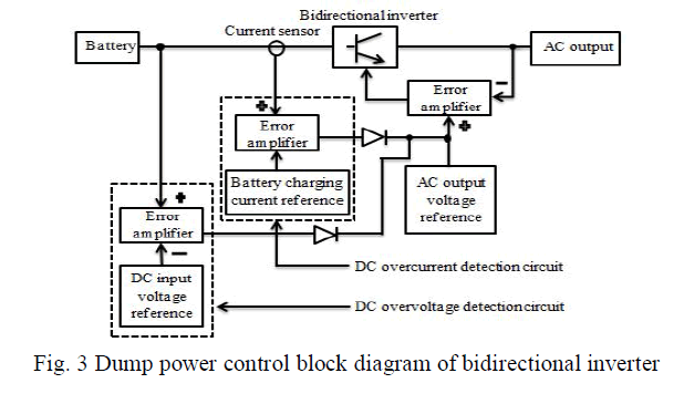
| Fig. 3 shows the dump power control block diagram of bidirectional inverter.The dump power control technique used in this paper stabilizes both charging current and charging voltage of the battery. | ||||||||||
 |
||||||||||
| This technique uses the natural energy effectively by reducing the needles dump power control and also responses quickly to fluctuating dump power. The overvoltage and overcurrent detection circuit stabilizes the charging voltage and charging current of the circuit. | ||||||||||
IV. RESULTS AND DISCUSSION |
||||||||||
| The detailed modelling of different components of the proposed system (shown in Fig.1) is discussed in this section. | ||||||||||
Mathematical Model of Wind Turbine |
||||||||||
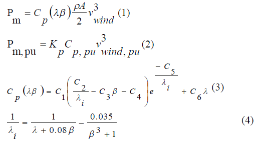
| The system governing the equations of wind turbine are given from (1) to (4). | ||||||||||
 |
||||||||||
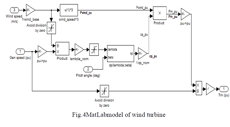
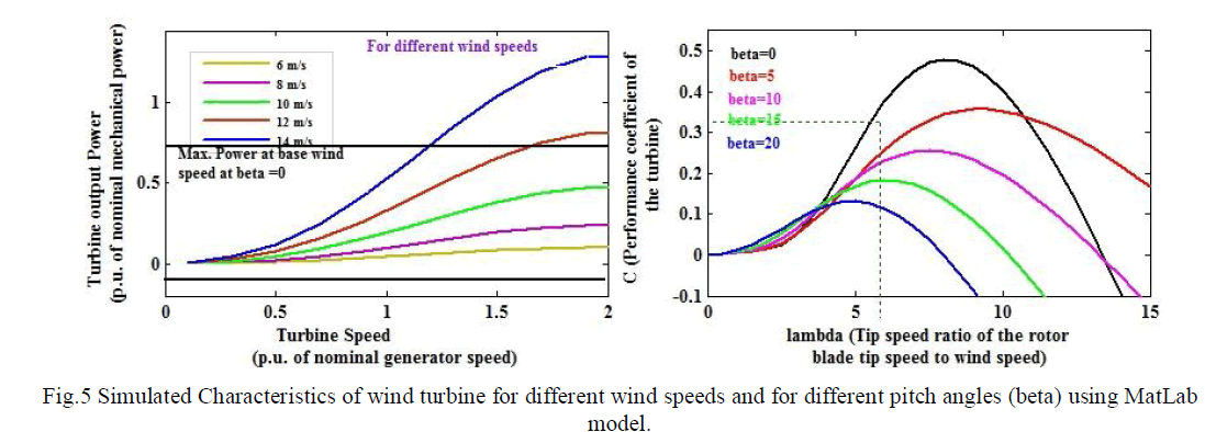
| Using the equations from (1) to (4) the wind turbine is modelled as shown in Fig. 4. The wind turbine is modelled using the parameters given in [17]. The base wind speed for the model is 12 m/s and the maximum power at the base speed is around 0.73p.u. Fig. 5 shows the simulated turbine power-speed characteristics for different wind speeds at constant pitch angle (beta=0) and C-lambda characteristics for different pitch angles (beta). | ||||||||||
 |
||||||||||
 |
||||||||||
| From the graph, it is observed that the maximum power at base wind speed is achieved for a pitch angle of zero degree. | ||||||||||
Mathematical Model of Solar Panel |
||||||||||
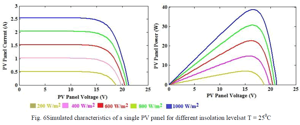
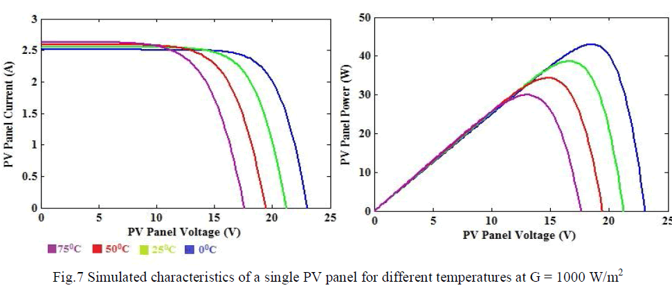
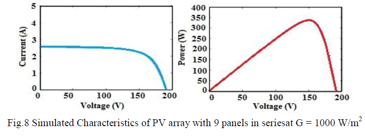
| The system governing the equations of solar panel is discussed in [16]. Using the equations present in [16], the solar PV panel has been modelled. For the solar panel there are 36 cells connected in series and one cell connected in parallel, the maximum open circuit voltage for the panel is 21.24 V and the maximum power is around 37.08 W. Fig. 6 shows the simulated characteristics of single PV panel for different insolation levels keeping temperature constant at 250C and Fig.7 shows the simulated characteristics of single PV panel for different temperatures keeping insolation constant at 1000 W/m2. A number of solar panels can be connected in series or in parallel based on the power requirement. Fig. 8 shows the simulated characteristics of 9 PV panel connected in series with a constant insolation of 1000 W/m2. As the voltage rating needed for the model is around 150V, there are nine panels connected in series and one panel connected in parallel (21.25×9). The array size of 9 ×1is designed as per requirement. From the graph it is observed that the voltage obtained is more when the no of series panel increases. As the voltage value increases the maximum power obtained also increases | ||||||||||
 |
||||||||||
 |
||||||||||
 |
||||||||||
Interfacing of Wind-Solar-Battery System |
||||||||||
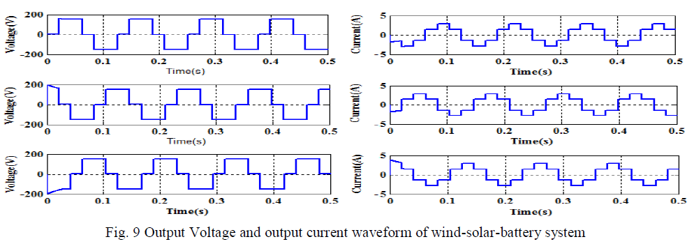
| PV and wind models discussed in previous sections are interfaced as in Fig. 1. Fig. 9 shows the output voltage and current waveform of the hybrid system. | ||||||||||
 |
||||||||||
| The obtained output voltage and current are approximately sinusoidal, using filters pure sine wave can be achieved, which can be supplied to the customers at the receiving end. | ||||||||||
 |
||||||||||
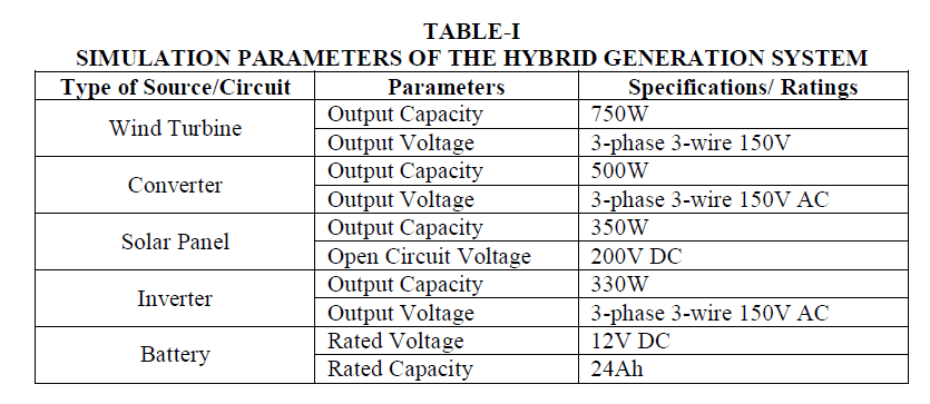
| Fig. 10 shows the frequency variation and reactive power consumption at the load side. The frequency variation is only by a small value of 0.0025 Hz .And it is also noted that with the variation in load, the frequency varies only by a very small value. The reactive power consumption at the load side is also small and it is only of the order of 10-12, and thus the real and reactive power is effectively controlled.Table I lists the specifications/ratings of the sources used in simulation. | ||||||||||
 |
||||||||||
V.CONCLUSION |
||||||||||
| The proposed standalone hybrid wind-solar power generation system is characterized by PLL control and dump power control. In case the power line is used as a media for data transmission, the line voltage amplitudes can be applied as a means of data transmission; thus, there is no requirement for installation of any optical fibre transmission line or power line carrier system through which harmonic signals are applied to power line. In addition, neither dump load nor dump load control device are necessary. Under the proposed dump power control, regulation of output is done without battery overcharging, and effective use of surplus power is made possible. This contributes to battery life extension and realization of a low-cost system. The frequency variation is very low and the reactive power consumption is also very low, the active and reactive powers are controlled more effectively compared to paper mentioned in the reference.The system, through ac system interconnection, will also allow flexible system expansion in the future. | ||||||||||
Tables at a glance |
||||||||||
|
||||||||||
Figures at a glance |
||||||||||
|
||||||||||
References |
||||||||||
|