ISSN ONLINE(2278-8875) PRINT (2320-3765)
ISSN ONLINE(2278-8875) PRINT (2320-3765)
T.Sripriya, Dr.V.Jeyalakshmi
|
| Related article at Pubmed, Scholar Google |
Visit for more related articles at International Journal of Advanced Research in Electrical, Electronics and Instrumentation Engineering
This paper explains about an optical pressure sensor based on MEMS technology that measures pressure with a higher accuracy and miniaturized design.The pressure sensor consist of Silicon diaphragm which is used to make the optical fibre pressure sensor, a more reliable model at required industrial working conditions. The design consists of an optical sensing membrane where the amount of deformation of the membrane directly accounts to the pressure applied. The design is built using COMSOL software. This paper also demonstrates the capabilities of COMSOL's frequency domain analysis with input and output ports.
Keywords |
| Mesa diaphragm, deformation |
INTRODUCTION |
| By employing the MEMS technology, a variety of optical MEMS pressure sensors based on Fabry-Perot interferometry have recently been proposed and fabricated. The major advantages of the optical sensors over the conventional electrical sensors include the immunity to electromagnetic interference, resistance to harsh environment and capability for multiplexing. Fabry-Perot interferometry is an optical component consisting of two partially reflecting parallel mirrors separated by a gap. With this robust structure, one can easily measure a loaded pressure by detecting the changes of the reflected or transmitted optical signals due to the shift of this gap. |
| Merits of the MEMS technology is proved in manufacturing the sensing elements with small and definite size. The measured response range, bandwidth, and sensitivity can be flexibly achieved by adjusting the size of sensing elements. Numerical simulations are common in describing optical experiments in micro-devices. Among them, the optical pressure sensors are capable of sensing at industrial applications. Over the last decade, silicon pressure sensors have undergone a significant growth and substantial research has been carried out on micro-machined, diaphragm-type pressure sensors. In most cases, these micro-electro mechanical devices are manufactured from rectangular or circular diaphragms. The development of high-performance diaphragm is of critical importance in the successful realization of the devices. In particular, diaphragms capable of linear deflection are needed in many pressure sensors. |
| In order to get the high sensitivity, the diaphragm thickness should be thin to maximize the load-deflection responses [1, 2]. On the other hand, thin diaphragm under high pressure may result in large deflection and nonlinear effects that are not desirable [3]. For the purpose of dynamic measurement, resonant frequency of the diaphragm is also an important parameter.It is therefore important to characterize the relationships among diaphragm. |
A. Description of optical pressure sensor |
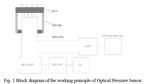
| The pressure-sensing element consists of a glass plate as shown in Fig.1 and a silicon diaphragm where a deep cavity is anisotropically etched into the upper surface and a shallow cylindrical cavity is etched into the underside surface. Because the refractive indices of the optical fiber, glass, air, silicon, and pressure medium are different, the light is coupled into the pressure sensor through optical fiber and reflected by each interface. The light interfered in multiple media is then coupled out of the sensor through the same optical fiber. The width of the air gap varies along with the loaded pressure due to the deflection of the silicon diaphragm [4]. Since, there exist a close relation between the width of the air gap and the reflection spectrum, it is expected that one can easily know the loaded pressure by measuring the spectrum shifts. |
 |
B. Proposed model of optical sensor |
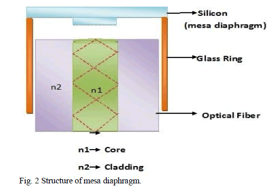
| The proposed F-P microcavity pressure sensing element, as shown in Fig.2, consists of two major components: a mesadiaphragm that serves as the moving mirror; an optical fiber that serves as the stationary mirror; and an air gap between the moving and stationary mirrors of the F-P micro cavity [5]. Light is introduced into the sensor from an optical fibre. One part of the incident light will be directly reflected by the fibre end face, and the other will come into the sensor and be reflected by the air-silicon interface. The reflected light will interfere with each other. When pressure is loaded onto the silicon diaphragm, the F-P cavity depth will change because of the deflection of the silicon diaphragm. The optical path difference in the F-P cavity will change, resulting in a change of phase of the sensor [6]. By measuring the shift of the reflection spectrum, it is expected that one can easily know the loaded pressure [7]. |
 |
C. Diaphragm Design and Load deflection |
| The load-deflection method is a well-known method for the measurement of elastic properties of thin films [8]. In this technique, the deflection of a suspended film is measured as a function of applied pressure. The load-deflection of the mesa structure of the diaphragm is obtained through simulation. The non-deflected and deflected image structures are shown in the Fig.3 and Fig.4 as follows. |
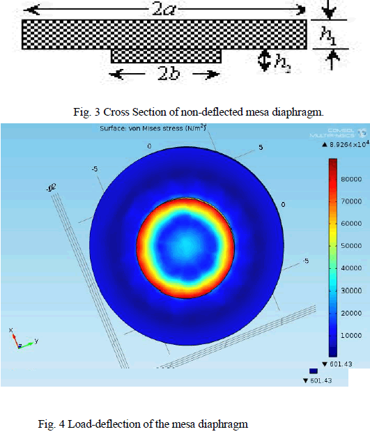 |
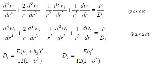
| Considering the radius of the circular membrane is a and the thickness is h1, the radius of the mesa is b and the thickness is h2. E is Young’s modulus, υ is Poisson’s ratio, and P is the loaded pressure. Due to the structural discontinuation of the circular membrane, the thickness of the membrane has the mutation. The differential equations are as follows: |
 |
| From the equations we get, |
 |
| Where ω1 is the deflection from 0 to b, ω2 is the deflection from b to a, r is the distance from random point to the center of circle. |
| The maximum deflection of the membrane (Fig.5) is as follows: |
 |
| The above figure infers the importance of the deflection caused when the pressure is applied. The deformed structure for a given value of pressure is shown in the figure above. |
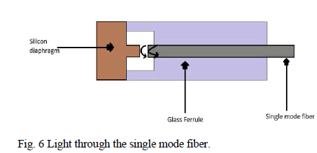
| The above are the mesa membranes designed using silicon material .This diaphragm is placed over fibre optic sensing structure. When pressure is applied over this diaphragm deformation occurs which in turn will result in variation in deflection of the light from the single mode fiber. This principle is explained using the Fig.6 below. |
 |
D. Light Input and response |
| After making deflection possible with simulation the next step would be giving light input to the non-deformed and deformed structures and obtain some variation when applied pressure is directly proportional to the deformation which in turn deviates the light reflected from non-deformed and deformed structure. |
| In comsol multiphysics there is an option of giving light input using mathematical PDE equation where we can modify to get the wave equation of light. The equation is given as follows |
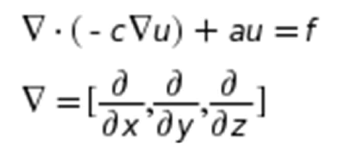 |
| The above equation is considered as the light input in comsol multiphysics by a following steps as shown in the window below. |
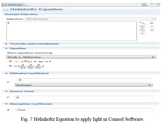 |
| After setting the parameters for light input the meshing should be done as the next step.The simulation is carried out for the inpur from both the directions.One as pressure from one direction of top of the membrane the other as light input from the songle mode fibre both the inputs are of specified values .The pressure value can be altered by varying the parameters at the pressure input values and the light input properties could be varied by the wave equation as shown in Fig.7. |
E. Results and Conclusion |
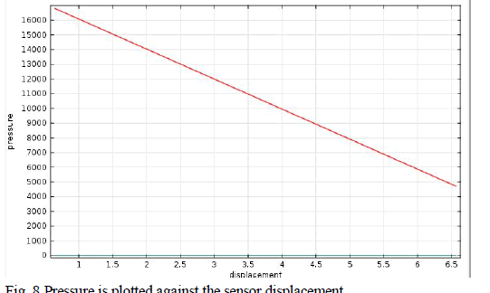 |
| The fitting line is having the linearity 0.9%, and the sensitivity (i.e., Change in cavity/loaded pressure) is good. As noted from the Fig.8, signal averaging effect is substantially reduced for the mesa pressure sensor by the flatnessenhancing diaphragm structure. This proposed Fabry Perot FP cavity will find applications to advantage small size and dense arrays, which play an important role in applications. |
References |
|