ISSN ONLINE(2278-8875) PRINT (2320-3765)
ISSN ONLINE(2278-8875) PRINT (2320-3765)
Anna Philo Antony1, Dr. Sankaran R2
|
| Related article at Pubmed, Scholar Google |
Visit for more related articles at International Journal of Advanced Research in Electrical, Electronics and Instrumentation Engineering
In this paper, the problem considered is an induction motor drive capable of operating certain types of loads demanding inverse torque – speed characteristics such as spooler load in a closed loop manner, where the mechanical power output remains nearly the same over the operating range. Such a drive requires a voltage-source inverter at variable frequency and also speed and current feedback configuration. The simulation of spooler drive system driven from a pulse width modulation (PWM) inverter fed induction motor is done using MATLAB/SIMULINK in a closed loop manner. The mechanical profile requires concurrent variation of torque and speed over a range depending on the mechanical dimensions of the take-up spooler and product line specifications. The control scheme is based on the field-oriented vector-control technique where decoupling of the torque and rotor flux variables is achieved and the desired stator current vector in a synchronous rotating frame of reference is generated. A d-q axis to a-b-c transformation followed by a hysteresis current controller is used to realize the desired stator currents. The simulation results indicate satisfactory performance of a typical spooler drive system over the full range of operation.
Keywords |
| Induction motor, Pulse width modulation inverter, Vector control, Spooler drive |
INTRODUCTION |
| The 3-phase cage induction motor is a natural choice for many drive applications in view of ready availability of ac supply and considerations of cost, reliability and ruggedness. Advances in power electronics have led to the development of variable speed drives based on the plain cage induction motor, where different types of torque-speed profiles are required. In many manufacturing processes the packing of long and continuous products like cables, ropes and similar products at the end of the production line is a frequently occurring problem. Here, final product to be wound requires an inverse torquespeed characteristic which is quite different from the normal requirements of a conventional drive system. In order to wind the product tightly on the spooler drum a tangential force is required which is attained by generating the necessary motor torque [6]. The required drive system is a variable speed one consisting of power electronics based inverter with a dc supply of 230V, along with feedback and control circuits driving the motor at variable frequency. A gear arrangement is required to step-down the speed also enables partial speed range at the drum. |
| Several studies have been done to find the appropriate technique for the control of variable-speed induction motor drives. The major criteria are fast and robust control of motor torque and flux, within a safe operating region. The content of this paper deals with simulation of spooler drive system along with vector control operating in closed loop using MATLAB/SIMULINK software. The simulation covers transformation of phase currents and flux linkages into the d-q axes frame for implementation of field-oriented control and realization of the stator currents through the inverse transformation, hysteresis current control and pulse width modulation scheme at the inverter. In the simulation the load torque and the reference speed are set for each layer of the product on the spooler drum of specified dimensions. The simulation results include the variation of torque and speed over the full history, simultaneous variation of inverter frequency and the current variations. |
RELATED WORK |
| E.D. Mitronikas, et. al [1] has proposed an improved sensorless vector control method for induction motor drives in which stator-flux estimation for the control method. The controllers are optimally tuned and the control algorithm is suitable for a low-cost microcontroller. Donald Grahame Holmes, et. al [2] has proposed a current regulation strategy for vector control of induction motor drive. Lekshmi .A, et.al [6] has proposed a closed loop operation of a spooler system driven from inverter fed BLDC in which an inverse torque-speed characteristic of the motor is studied. Rajneesh Mishra, et.al [9] through the paper has discussed about the study of transient performance of inverter fed induction motor using both V/f (conventional method) and vector control method. Ansari A. A, et.al [14] has provided a mathematical model for asynchronous machine. The model is proposed for low power motor and to minimize errors due to testing and design mistakes. |
FIELD-ORIENTED CONTROL OF INDUCTION MOTOR |
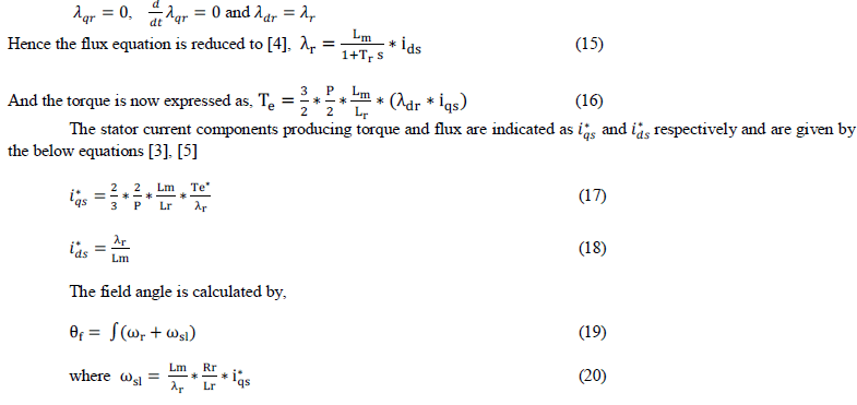
| Field-oriented control (FOC) is analogous to the energy conversion process in a DC machine, where the field flux is always in quadrature with the armature flux, allowing independent variation of flux and torque. As a result, a DC machinelike performance can be attained in the AC machine through the Field- Oriented Control (FOC) technique [9]. This can be achieved by aligning the phase current on the stator with respect to the rotor flux by sensing or estimating the field angle of the rotor. The modeling of induction motor using FOC consists of the following steps: Induction motor modeling in synchronous reference frame, Reference current generation and Pulse width modulation for VSI. |
INDUCTION MOTOR MODELING |
| The following assumptions are made to derive the dynamic model of induction motor [3] |
| - Balanced stator and rotor windings, with sinusoidally distributed mmf. |
| - Saturation and parameter changes are neglected. |
| - The stator and rotor circuits are referred to the stator side with equivalent parameter values. |
| - The interaction between rotor and stator fluxes is indicated by mutual inductance. |
| - Uniform distribution of air gap between rotor and stator. |
| Depending upon the application, the induction motor can be modeled either in a stationary, rotor or synchronously rotating reference frame [3], [5]. In this paper the motor modeling is done in synchronous reference frame, where the variables appear as DC quantities facilitating smooth control. Here, the three phase variables (a-b-c variables) are first transformed into α-β frame using Clark’s transformation and the d-q axis variables are obtained using Park transformation, thereby facilitating controller design and evaluation of transient phenomena in the drive system [4], [5].The 3 phase stator voltages of an induction motor are transformed into two phases by the following equation [3]. |
 |
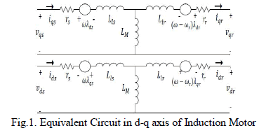
| The Fig.1 shows the equivalent circuit diagram of induction motor in the d- axis and q- axis separately for both stator and rotor that satisfies the equations (3-6). |
 |
| The stator and rotor voltage equations in d-q axes in terms of flux linkages are now expressed as follows: |
 |
| The stator and rotor flux linkage equations in d and q axes are given below, |
 |
| The electromagnetic torque of induction motor is obtained by[5]. |
 |
| where P and J represents number of poles and moment of inertia respectively[7] |
IMPLEMENTATION OF FIELD-ORIENTED CONTROL |
| Vector control technique of the IM entails varying not only the magnitude but also phase of the stator currents. This is done by controlling the stator current components ids and iqs indicated as a space vector, in d-q axes rotating frame as shown in Fig.2.Tthe rotor flux vector is evaluated by either of the strategies mentioned below [1], [4], [5]. |
| a) Direct Field Oriented Control (DFOC) - In this strategy a sensor based measurement of rotor flux vector is carried out using stator variables and parameters. |
| b) Indirect Field Oriented Control (IFOC) - In this strategy rotor flux vector estimation is carried out for rotor flux and the slip speed for calculating the field angle(θr). |
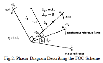 |
| Considering the d-q model of the induction machine in the synchronous reference frame, the field-oriented control implies that the stator current component ids is aligned with the rotor field and is in quadrature with the iqs component. This is done by aligning the rotor flux to the d-axis by locking the phase of the synchronously rotating reference frame, as illustrated in the Fig.2. |
 |
SPOOLER DRIVE SYSTEM |
| The spooler drive system comprises of a large drum fixed on a shaft and a gear box through which the drum is coupled to the induction motor as shown in Fig.3. A similar problem of operating a spooler drive based upon a BLDC motor has been proposed by Lekshmi. A et al [6]. Here, the product line (for example rope or cable) is wound smoothly on the spooler drum in a layer-wise manner at a specified speed till a specified product line length is accommodated. |
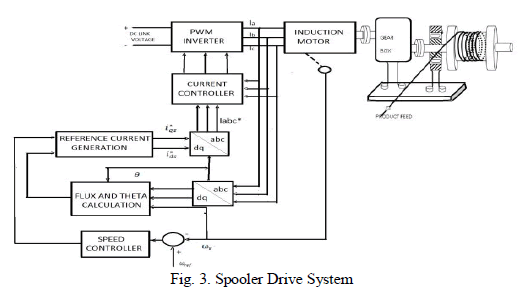 |
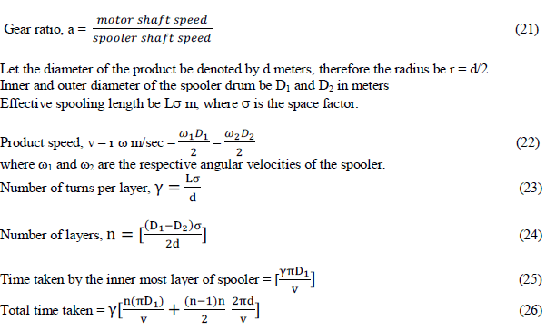
| Motors required for spooling contains gear boxes to drive the load and to step-up the motor torque so that the load speed is reduced. For motor with gear ratio ‘a’, the torque at the spooler is a times motor torque (Tm) and the motor speed is a times the load speed [6]. |
 |
SIMULATION OF SPOOLER DRIVE SYSTEM |
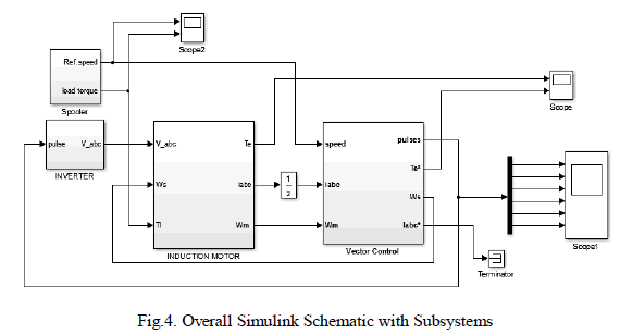
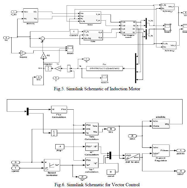
| The simulation of a spooler drive system driven from pulse width modulated inverter fed induction motor along with speed and current feedback is done in closed loop using MATLAB/SIMULINK. The three phase voltage source inverter comprises of 6 Insulated Gate Bipolar Transistors (IGBT) in a bridge configuration is fed from a dc link of 230V. The closed loop control scheme consists of the mathematical modeling of induction motor [8], 6-pulse inverter and speed and current controller for generating to satisfy the required logic, sequence and timing for triggering the gate signals for IGBT[12], [13], [14]. Here a speed error is obtained by comparing actual speed with the reference speed. An actuating signal is obtained as the output of PI controller which is fed by an error signal. Now the reference torque and current signals are obtained from a user-defined subsystem using equations (16), (17) and (18). |
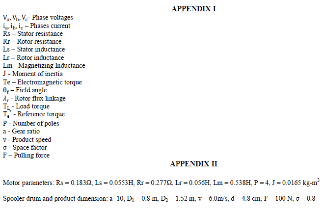
| The simulation run has to cover a fairly long history, covering a startup and the spooling action covering six successive layers of the product. During this run the torque and the speed demanded by the spooler load are calculated layer-wise along with the time instants where change-over to the next layer is also specified. The above data as simulation parameters are shown in Table1 along with the set of reference speed and torque values. |
 |
SIMULATION SCHEMATIC |
 |
 |
SIMULATION RESULTS |
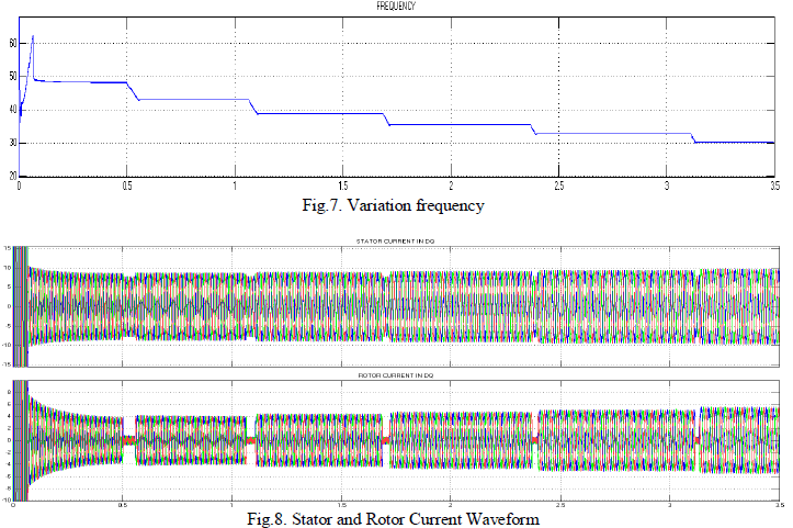
| The spooler drive system operating at normal load conditions is simulated for a load torque ranging between 4Nm to 6.4Nm and motor speed ranging from 1430 rpm to 900 rpm. The results include the variation of frequency, rotor speed, electromagnetic torque, and stator and rotor currents with respect to the spooling time in sec. Since the physical spooling interval covering 6 layers of the product takes about 40 sec, it is necessary to introduce a time scale of 0.1to introduce the load changes in the simulation run. |
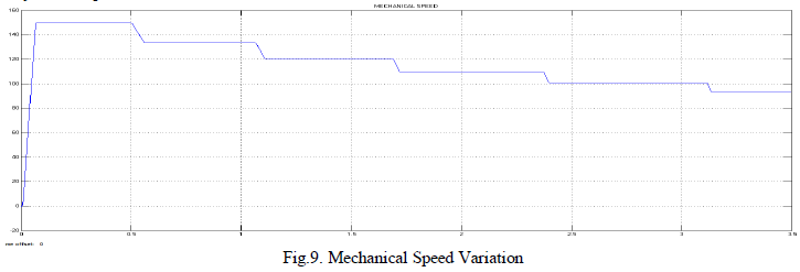
| The performance of the drive system is characterized by variable frequency and variable voltage operation of the sixpulse inverter, along with maintaining field-orientation. The variation of stator phase currents (ia, ib, ic), electromagnetic torque Te and mechanical rotor speed ωr are obtained from the Simulink run. The variation of the stator frequency is shown in Fig.7. This implies that the drive system is capable of running at variable frequency due to variation in speed at different layer of the product. The results prove that a better and faster response is achieved than in the conventional method. |
 |
| The poor dynamic torque and low speed accuracy due to the conventional V/f method has been improved in this method and provides a better response. The simulated variation of speed and torque are shown in Fig.9 and Fig.10 respectively. In the speed waveform it is observed that the speed response is faster and attains the desired set values for the each layer of the product wound on the drum. |
 |
 |
| The torque and speed waveforms imply that an inverse torque-speed characteristic is obtained for the take-up spooler drive system. |
CONCLUSIONS |
| The spooler drive problem is formulated and the data are specified using industry requirements for a specific product line. The formulation makes use of the theoretical equations governing field oriented control and incorporates speed and current feedback. A detailed schematic covering a six pulse inverter fed from a 230V dc source, the induction motor model, user-defined blocks to ensure field orientation along with speed and current feedback loops are created in SIMULINK. These simulation results covering the full history of the spooler operation results are presented graphically. These results indicate the suitability and satisfactory performance of the vector controlled drive system. |
 |
References |
|