ISSN ONLINE(2319-8753)PRINT(2347-6710)
ISSN ONLINE(2319-8753)PRINT(2347-6710)
Deebika.R1, Shankarganesh.R2
|
| Related article at Pubmed, Scholar Google |
Visit for more related articles at International Journal of Innovative Research in Science, Engineering and Technology
Many photovoltaic inverter designs make use of a buck-boost sinusoidal waveform. This waveform is unfolded by a low frequency switching structure to produce a fully sinusoidal waveform. The cuk converter could offer more advantages over the buck-boost in photovoltaic inverter applications. Unfortunately, the Cuk converter is difficult to control using classical methods. A perfect closed loop design is essential for stable operation of Cuk converters. Due to these stability issues, Cuk converter based designs often require stiff low bandwidth control loops. In order to achieve this stable closed loop performance, traditional designs invariably need large, unreliable electrolytic capacitors. In this project, a microinverter with PI and fuzzy based Cuk converter approach is presented which enables the designer to make use of the Cuk converters advantages, while improving the control difficulties. This control method allows the selection of passive components predominantly based on ripple and reliability specifications while requiring only one state reference signal. This method becomes smaller and more reliable.
Index Term |
| Cuk converter, PI and Fuzzy controller |
INTRODUCTION |
| While fossil fuel exhaustion and greenhouse effects are widely concerned around the world, one of the most important issues toward these problems is to find alternative energy for long-term solutions. Green energy offering the promise of clean and abundant energy gathered from self renewing sources such as solar energy, geothermal energy, and wind source is broadly developed. Solar cells are unique in that they directly convert the incident solar irradiation into electricity. Photovoltaic (PV) power management concepts are essential to extract as much power as possible from the solar energy. PV energy systems are being extensively studied because of their benefits of environmental friendly and renewable characteristics. Typically, several PV panels are connected in series to provide a high-voltage output. However, the PV panels often work in mismatching conditions due to different panel orientations and shadowing effects. This mismatching problem thus reduces the power production of the whole PV string. To overcome the drawback, several literature works have proposed a module-integrated converter concept. Individual maximum power point tracking (MPPT) converters are attached to each PV panel for extracting its maximum power. Such a PV module composed of a PV panel with an individual dc–ac inverter is called a solar microinverter. |
| A. Conventional Block Diagram |
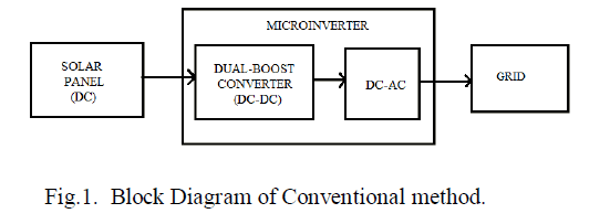
| Conventional method is shown in the Fig.1. Photovoltaic power is regarded as a chief source of energy in several countries with high solar power density. The main obstruction for reach of solar PV systems is their low efficiency and high capital cost. In existing system Perturbation and Observation (P&O) algorithm is used for maximum power point tracking as it has the potential to adjust the solar array reference voltage to attain maximum power point. But, this produces oscillations in voltage conversion. The isolated dual boost converter is one of the existing efficient converters in PV systems. One main drawback in this converter is switching loss is high. |
 |
 |
 |
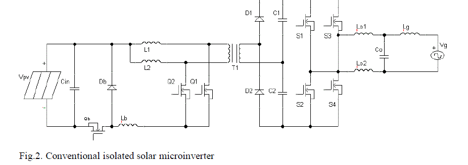
| B. Isolated Dual-Boost Circuit The solar micro inverter consist of an isolated dual boost converter with secondary voltage doubler, a polarity selector and an output LC filter. There are two operating modes for the conventional dual boost circuit. The minimum duty cycle of Q1 and Q2, and Vpv denotes the PV panel voltage. Under this operation mode, the buck switch Qb is always on. PV panel voltage Vpv is fed directly to the input of the interleaved dual boost circuit. The duty cycle δboost of Q1 and Q2 is modulated as (2) to provide a rectified sinusoidal waveform |Vg| on capacitors C1 and C2 that is connected with the ac grid system via the polarity selector and the LC output filter. Because the polarity selector is operated at the line frequency and switches at zero crossing of the ac grid voltage, the switching loss can be neglected. Assuming that the conduction losses on power devices of the inverse buck circuit and the polarity selector can be ignored, the only loss of the studied isolated solar microinverter is due to the single-stage power conversion of the isolated dual-boost circuit. |
II.SYSTEM DESCRIPTION |
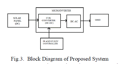
| In the proposed method, for microinverter the isolated converter is replaced by the DC-DC Cuk converter is shown in the Fig.3. In this project the PI and fuzzy controller is included additionally for maximum power point tracking. Energy flow is bidirectional with the help of a diode and a switch. The power flow is continuous because of the capacitor. The advantage of this method is to reduce switching loss. It reduces ripples and EMI. It results in improved efficiency |
 |
| In recent years the need to harness renewable energy has become more important. In order to become commercially viable the cost per kilowatt-hour of these energy sources must fall. Installation and maintenance costs contribute significantly to the overall cost of photovoltaic (PV) energy production. With ever more stringent limitations on the amount of conducted and radiated electromagnetic interference (EMI) manufacturers will only increase unit costs. Studies have suggested that up to 50% of the initial system cost, excluding that of the panel is associated with the inverter. Designing a stable Cuk converter, using classical control loop design methods is not an easy task. In order to ensure an adequate phase margin for stable operation, the value of the reservoir capacitor becomes very large to a point where only electrolytic capacitors are available in those sizes. Unfortunately this capacitor also needs to support the full-load current and hence forms a big reliability problem for Cuk topology converters. Electrolytic capacitors are on average thirty times less reliable than non-electrolytic types under identical conditions, and reliability decreases with increasing component values. Through the use of PI and fuzzy logic controller, the need to use expensive, large and high ESR electrolytic capacitors in the Cuk design can be eliminated and improvements in reliability are envisaged. |
 |
| In addition, the Cuk converter possesses continuous voltage and current at both input and output terminals, which is achieved with a low component count and size. A Cuk converter is, therefore, an ideal choice to reduce costs in an environment of strict EMI regulations, offering potential savings in both installation and servicing costs. The original Cuk topology can be extended using integrated or coupled magnetic in order to provide voltage and current ripples of zero at the input and/or output terminals, respectively, thus improving EMI performance still further. Good inverter strategies using the Cuk converter with advanced magnetic structures have been presented. Traditionally, AC sinusoidal outputs with low harmonic content have been achieved using a high frequency H-bridge configuration and reactive filtering. Designs of this type generally require some form of internal voltage boosting, as voltages available from PV panels are frequently limited to cost, efficiency, and safety reasons. The voltage boosting is achieved either before the H-bridge using a DC–DC converter, or after the H-bridge using a line-frequency step-up transformer. It is argued that reducing the number of high frequency switches, and the switching stresses on them, would improve the efficiency as well as the robustness of PV systems. One widely used inversion method which requires few high frequency switches uses a single quadrant power supply to form a series of sinusoidal half-waves of one polarity. |
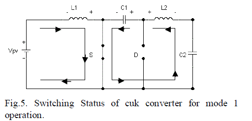 |
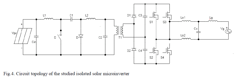
| At, the switch S is ON. The current through inductor L1 is increases. At the same time, the capacitor voltage VC1 reverse biases the diode D and turns it off state. The energy of the capacitor is discharges through S, C2 and L2. Therefore inductor current IL2 increases. The input supply feeds energy to inductor L1 and causing inductor current IL1 also increases. The voltage across the inductor L1 is Vpv. the voltage across the inductor L2 is Vc1- Vo. The Fig.5 shows equivalent circuit mode 1 operation. |
| MODE 2: |
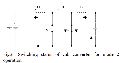 |
| The switch s is off, the inductor current flow through the diode. The capacitor C1 is charged through the diode by energy from both the input and L1. The inductor current iL1 decreases because of Vc1 is larger than Vpv. the energy stored inductor L2 is transmitted to load. Therefore inductor current IL2 also decreases. Here, the capacitor C1 is used for transferring energy from the source to load. The voltage across the inductor L1 is –Vpv. The voltage across the inductor L2 is –Vo. |
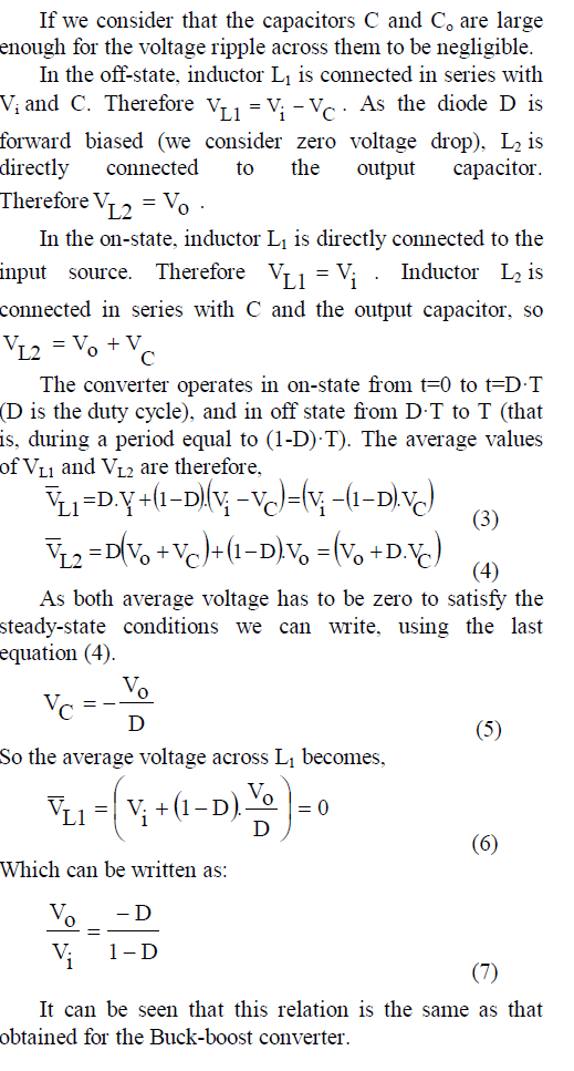
| A. Continuous ModeIn steady state, the energy stored in the inductors has to remain the same at the beginning and at the end of a commutation cycle. The energy in an inductor is given by |
| This implies that the current through the inductors has to be the same at the beginning and the end of the commutation cycle. As the evolution of the current through an inductor is related to the voltage across it, |
 |
| It can be seen that the average value of the inductor voltages over a commutation period have to be zero to satisfy the steady-state requirements. |
 |
| B. Discontinuous Mode Like all DC-DC converters Cuk converters rely on the ability of the inductors in the circuit to provide continuous current, in much the same way a capacitor in a rectifier filter provides continuous voltage. If this inductor is too small or below the "critical inductance", then the current will be discontinuous. This state of operation is usually not studied in much depth, as it is not used beyond a demonstrating of why the minimum inductance is crucial. The minimum inductance is given by, |
 |
| Where fs is the switching frequency. |
 |
II. SIMULATION RESULTS |
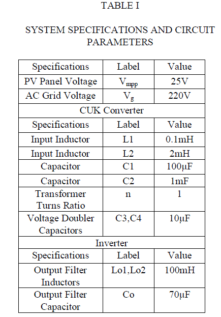
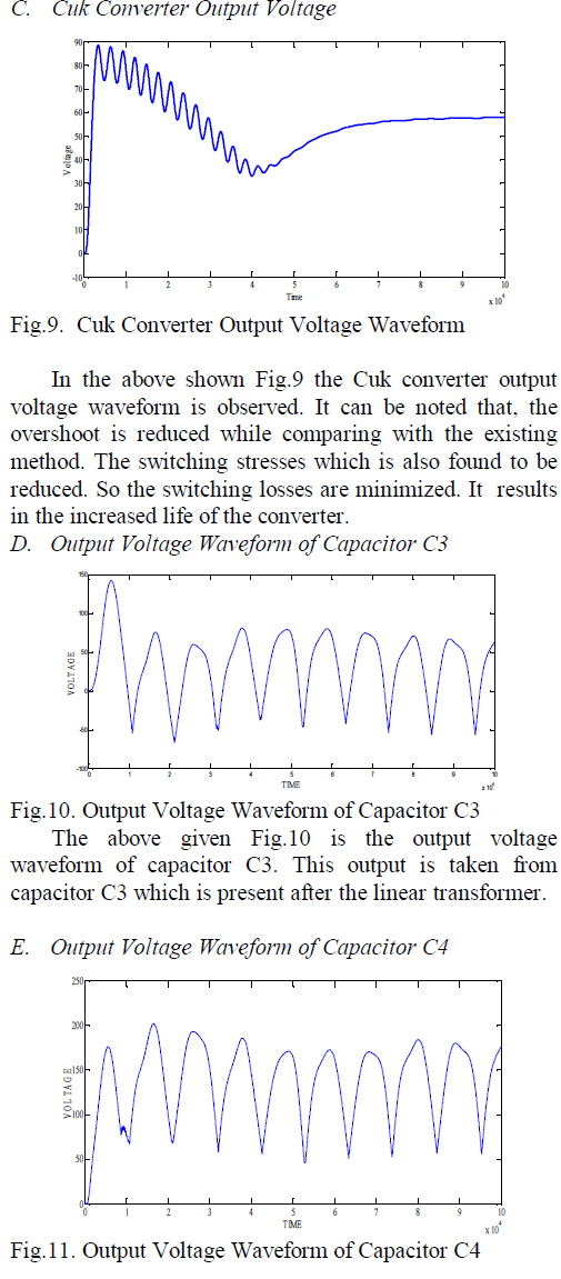
| Table I shows the system specifications for the photovoltaic integrated cuk converter for grid connected microinverter. The simulation circuit of the proposed method includes all the details of the simulation. From the solar PV panel, 25V is obtained which is given as the input of the Cuk converter. It boosts up to 60V as a constant. Using PI and fuzzy controller, the Cuk converter is controlled. |
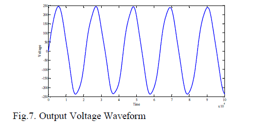
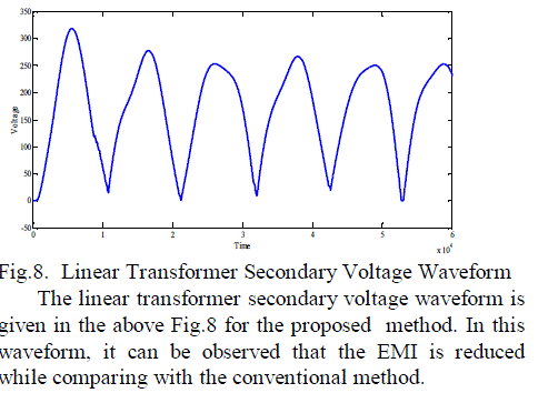
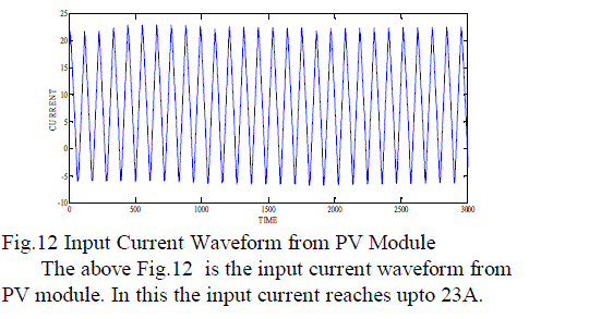
| The switching stress can reduced by using the Cuk converter. The EMI can also reduced by using the Cuk converter. So the efficiency of converter is increased. Then it is given to the linear transformer and it inverts DC to AC. It is then connected to the grid. The simulation results are shown below. The simulation results of an output waveform of the proposed method..It includes the output voltage waveform, linear transformer secondary voltage waveform and the dual boost output voltage waveform. |
| A. Output Voltage Waveform |
 |
 |
 |
 |
IV. CONCLUSION |
| An isolated DC-DC Cuk converter is investigated and designed for microinverter in this project. The PI and fuzzy controller are used in this project for maximum power point tracking. Energy flow is bidirectional with the help of a diode and a switch. The simple inverter topology, owing to the reduced number of main power devices and less power-conversion stages, potentially leads to lower cost and high power density design. The simulation and experimental results verify the operation and shows the output voltage. |
References |
|