ISSN ONLINE(2278-8875) PRINT (2320-3765)
ISSN ONLINE(2278-8875) PRINT (2320-3765)
Dr. M.Z.Kurian1, Ashwini.S.Shivannavar2, Anisha Abraham3
|
| Related article at Pubmed, Scholar Google |
Visit for more related articles at International Journal of Advanced Research in Electrical, Electronics and Instrumentation Engineering
The increasing opportunity of 3 dimensional silicon based integration technology has given a wide prospect for architecture innovations. One enhancement is in the expansion of 2 dimensional mesh chip-multiprocessor architectures into three dimensions. The paper mainly focuses on providing a efficient routing algorithms for 3-D mesh networks. The main provision of this paper is a new routing algorithm for 3 dimensional mesh networks called as randomized partially-minimal (RPM) routing. RPM has been found to achieve optimal worst-case throughput for 3 dimensional meshes In addition, a modification of RPM called randomized minimal first (RMF) routing is introduced, which leverages the inherent load-balancing properties of the network traffic to further reduce packet latency without compromising throughput.
Keywords |
| 3 dimensional ICs, on-chip networks, routing algorithms. |
INTRODUCTION |
| There has been considerable discussion in recent years on the benefits of three dimensional silicon based integration in which multiple device layers are placed on top of each other with direct vertical interconnects tunneling through them. 3-D integration promises to address many of the key challenges that arise from the semiconductor industry’s relentless push into the deep Nano-scale regime. Recent advances in 3-D technology in the area of heat dissipation and microcooling mechanisms have alleviated thermal concerns regarding stacked device layers. Many proposed 2-D tiled chipmultiprocessor architectures have relied on a 2-D mesh network topology as the triggering communication. Extending mesh based tiled chip-multiprocessor architectures into three dimensions represents a natural progression for exploiting 3-D integration. The focus of this paper is on providing efficient routing for such 3 dimensional mesh networks. RPM achieves near-optimal worst-case throughput in 3-D mesh networks by load-balancing packets uniformly across all vertical layers and routing minimally on the horizontal layers. However, RPM is not minimal in terms of latency since it needs to route packets to a randomly chosen intermediate layer. In this section, we present a destination-aware layer selection technique that can reduce the latency of RPM when the traffic is inherently load-balanced, such as uniform random traffic. The randomized variant of RMF is better suited for symmetric mesh networks because it balances the channel load equally between the X, Y, and Z channels. However, randomized RMF requires a separate set of counters for load balancing flits along each of the X, Y, and Z dimensions. As in the case of RPM, randomization is not needed for practical asymmetric topologies where load-balancing along the shorter dimension leads to higher throughput. |
RPM ROUTING |
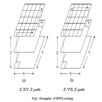
| For practical asymmetric mesh topologies where the number of device layers (Z dimension) is expected to be fewer than the number of nodes along the edge of a layer (X and Y dimensions), two-phase routing along the short Z dimension and minimal routing along the longer X and Y dimensions results in highest average-case throughput. On the other hand, for symmetric 3-D mesh topologies, a randomized version of RPM where Z-XY/YX-Z, X-YZ/ZY-X, and YXZ/ ZX-Y routings are used with equal probability yields the highest average-case throughput as it balances channel load along all three dimensions. Randomization does not change the worst-case throughput of RPM because each one of the three routing algorithms combined has the same near-optimal worst-case throughput. |
 |
| A. Virtual channel and deadlock |
| Virtual channels (VCs) are needed in on-chip routers to avoid cyclic resource dependencies, like buffer dependencies, which can result in deadlocks. If RPM is implemented by load-balancing only along one dimension (lets say the Z dimension), two virtual channels per physical channel are sufficient to achieve deadlock-free routing. One approach is to divide the input buffers on links along the Z dimension into two VCs—VC-0 reserved for phase-1 of Z routing and VC-1 reserved for phase-2 of Z routing. The buffers on links along the X and Y dimensions are also divided into two VCs—VC- 0 reserved for packets using X-Y routing and VC-1 reserved for packets using Y-X routing. This VC allocation scheme ensures deadlock-free operation as the corresponding channel dependency graph is acyclic. The randomized version of RPM involves load-balancing packets along each dimension with equal probability and routing minimally along the two remaining dimensions, can be made deadlock-free using three VCs. This VC allocation scheme results in an acyclic channel dependency graph for randomized RPM. This router architecture is a direct extension of 5-port routers used in 2- D mesh networks, with the addition of two extra ports for vertical communication. At each input port, buffers are organized as separate FIFO queues, one for each VC. Flits entering the router are placed in one of these queues depending on their VC ID. The router is generally pipelined into five stages comprising route computation, VC allocation, switch allocation, switch traversal and link traversal. The route computation stage determines the output port of a packet based on its destination. This is followed by VC allocation where packets acquire a virtual channel at the input of the downstream router. A packet that has acquired a VC arbitrates for the switch output port in the switch arbitration stage. |
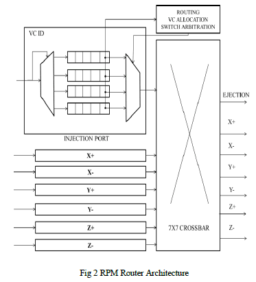 |
| Flits that succeed in switch arbitration traverse the crossbar before finally traversing the output link to reach the downstream router. Head flits proceed through all pipeline stages while the body and tail flits skip the route computation and VC allocation stages and inherit the output port and VC allocated to the head flit. The tail flit releases the reserved VC after departing the upstream router. In order to implement a new routing algorithm like RPM in place of existing routing algorithms like DOR, only the route computation and VC allocation stages of the router pipeline need to be modified. |
| B. Choosing an intermediate layer |
| Since RPM involves load-balancing packets to a randomly chosen intermediate layer, some extra logic needs to be added to the baseline architecture to choose an intermediate layer. In most NoCs there is a strict requirement that all flits of a packet have to arrive at the destination in-order. Hence, load-balancing across layers has to be carried out at the granularity of packets and not flits. The logic for picking a random intermediate layer can be implemented using a simple linear feedback shift register (LFSR), which is often used to generate a pseudo-random sequence. Let us assume that packets are load-balanced uniformly along the Z dimension. If kz is the number of layers in the topology, an LFSR with log2kz bits is sufficient to generate a pseudo random sequence of kz layers. In order to increase the randomness of the LFSR sequence for small values of kz, a pseudo-random sequence with greater than kz bits can be generated and the intermediate layer can be chosen by performing a modulo-kz operation on the generated sequence. For example, in a 8x8x4 mesh topology with 256 nodes, layer load balancing can be carried out using the last two bits of a 8-bit a pseudorandom sequence. To ensure that the random number generators at the different nodes work independently the LFSR at a node can be initialized to the unique 8-bit node address. In general, for a network with N nodes, a log2N bit LFSR can be used to pick an intermediate layer. Each LFSR can then be initialized to an unique initial state (which is the unique log2N bit node address) resulting in different pseudo-random sequences at different nodes. In the special case when the X and Y coordinates of the destination are same as the corresponding coordinates of the source, the decision of the LFSR is overridden and the intermediate layer is forced to be the Z coordinate of the destination. If the pseudo-random sequence generation process and the packet injection process (determining packet size) are independent, over a period of time the number of flits sent to different layers is expected to be equal. If more accurate load-balancing is desired, a more sophisticated credit-based load balancing scheme can be employed for multi-flit packets. In this technique, every node in the network maintains kz credit counters, one for each layer, all initialized to 0. The first layer with non-negative credits is always chosen to route a packet. When layer l* is selected to route an M flit packet, the credit counter corresponding to is decremented by M- M/kz since layer l* receives an excess of M- M/kz flits compared to ideal flit-level load-balancing across layers. At the same time, counters corresponding to all other layers are incremented by M/kz to account for the flit deficit with respect to ideal flit-level load-balancing. The layer selection approach requires counters at each router to keep track of the credits associated with each layer. The counter size depends on the maximum packet length and the number of layers in the topology. If the maximum packet length is flits, the credit values can range from –L to (kz-1)L. As explained earlier, when the X and Y coordinates of a packet’s destination are same as those of the source, the Z coordinate of the destination is forced to be the intermediate layer in order to remove loops. The counters remain unchanged in this special case as no extra load is added to links along the X and Y dimensions of the destination layer. After an intermediate layer is chosen at the time of packet injection, the intermediate layer number must be included in the packet header to enable the route computation stage to route packets to the appropriate layer. The intermediate layer selection can be carried out one cycle in advance to avoid increasing the critical path delay of the router. |
| C. Choosing xy/yx routing |
| RPM uses minimal XY or YX routing with equal probability on each horizontal layer. The logic to choose XY or YX routing paths, which uses a single signed counter to keep track of the excess/deficit of flits using XY or YX routing. The decision to use XY or YX routing can be taken before packet injection, in parallel with intermediate layer selection, and the routing decision can be stored as a part of the packet header. This approach avoids adding extra delay at intermediate routers. |
| D. Routing and vc allocation |
| In a baseline router using dimension-ordered routing, the routing can be decomposed into the X, Y and Z dimensions. The route computation stage first routes a packet along the X dimension, followed by the Y dimension and finally, the Z dimension. For packets at the injection, X+ and X- inputs of a router, the route computation logic needs to determine the X, Y and Z offsets to a packet’s final destination and choose the first productive dimension. For packets at the Y+ and Y- inputs, the routing decision is based on the Y and Z offsets to the packet’s final destination and for packets at the Z+ and Z- inputs, the decision is based only on the Z offset. |
| Next, we describe one possible high-level implementation of the route computation stage for asymmetric 3-D mesh networks where packets are load-balanced only along the dimension. A packet is injected into either VC set 0 or VC set 1 at the port. The routing decisions for packets at different input ports and input VCs are taken as follows: For packets at any VC set of the port and VC set 0 of the and ports, the offset along the Z dimension to the intermediate layer is determined along with the X and Y offsets to the final destination. If the packet has reached the destination, it is simply ejected from the network. If the Z offset to the intermediate layer is non-zero, packets are routed along the Z dimension on VC set 0. On the other hand, if the Z offset is zero and a packet is chosen to use XY routing, the packet is forwarded to the output port along the X dimension on VC set 0, if the X offset is non-zero. If the X offset is also zero, the packet is forwarded to the output port along the Y dimension on VC set0. Alternatively, if the packet is chosen to use YX routing, it is forwarded to the output port along the Y dimension on VC set 1, if the Y offset is non-zero. If the Y offset is also zero, the packet is forwarded to the output port along the X dimension on VC set 1. |
| For symmetric mesh topologies, a randomized version of RPM that needs three sets of VCs is used. In addition to choosing an intermediate layer and the order of dimension traversal within a layer, the randomized variant also needs to select one of X, Y or Z dimensions for load-balancing packets. This decision has to be taken during packet injection and stored in the packet header. The route computation at intermediate routers can then be divided into three parallel planes to handle, X-YZ/ZY-X, Y-XZ/ZX-Y, and Z-XY/YX-Z routing, based on the routing plane chosen for a packet at the time of injection. The VC allocation stage looks at the input port, the input VC set, and the output port of a packet to determine the output VC set. The output VC set is equal to input VC set + 1 if the packet is making a YX, ZY or ZX turn. Otherwise, the output VC set is equal to the input VC set. |
SYSTEM IMPLEMENTATION |
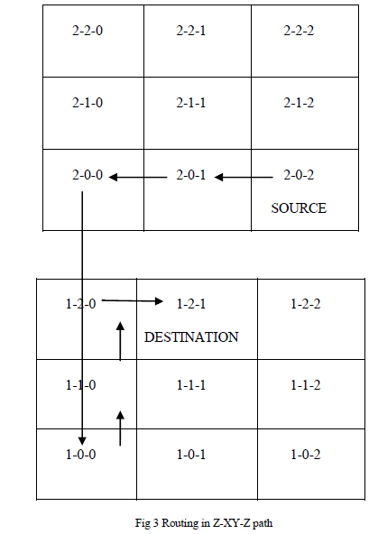
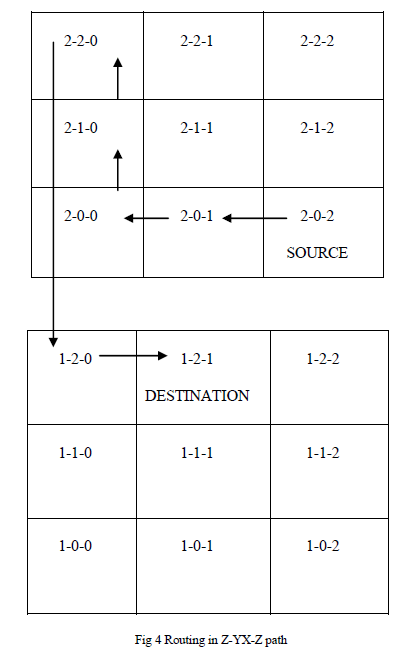
| The system implementation of the project has been able to develop the programming code for both Z-XY-Z and ZYX- Z path in the router architecture. In Z-XY-Z route path the source is routed along X dimension and then along Y dimension. In the latter case the path is routed along Y dimension and then along X dimension. We consider a 3 X 3 layer with 9 routers in each layer. Three layers are been considered in the current example. Each layer is categorized as its column and row number along with its layer number in order to distinguish each router separately. The first number denotes the layer, the second denotes the row and the third its column number. In this way the transmission process can be easily managed. Here, we consider the source as router 2-0-2 and the destination as the router 1-2-1. The packet is transmitted with the help of selection line that has been stored in the header file of the packet being transmitted. The packet can be transmitted along either routing paths with ease. |
 |
 |
RESULTS & OUTPUT WAVEFORM |
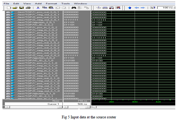 |
| In figure 5 we can see the input data been initialized from the router 2-0-1. Hence the router is considered as the source node in the current network of data transmission. |
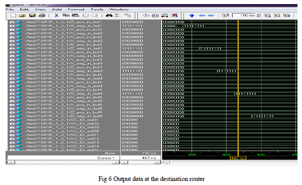 |
| In figure 6 we can see the output data been reached in the router 1-2-1. Hence the router is considered as the destination node in the current network of data transmission |
CONCLUSION |
| The analysis of these topics has helped us to understand the designing aspect of the 3D mesh routing and its advantages that come across on routing in the network. Above we have analyzed the various ways through which the routing could be done and what are its effects on load balancing of the chip. The number of virtual channels required for various forms of routing also helps us to decide and obtain our necessity as the prior role. In focus with the obtained knowledge we have designed the new proposed design architecture of routing using randomized minimal routing technique for 3D chips that helps us to provide near optimal worst-case throughput. At present, the router architecture has been programmed, simulated and the output waveform has been verified for both Z-XY-Z and Z-YX-Z routing paths. |
References |
|