ISSN ONLINE(2278-8875) PRINT (2320-3765)
ISSN ONLINE(2278-8875) PRINT (2320-3765)
N Narasimhulu1, K N Jayasree2 P Peddareddy3
|
| Related article at Pubmed, Scholar Google |
Visit for more related articles at International Journal of Advanced Research in Electrical, Electronics and Instrumentation Engineering
STATCOMs are sometimes essential for voltage support in transmission networks. They can also be used for un-interrupted operation of wind farms equipped with doubly fed induction generators (DFIGs) during grid faults. The only disadvantage of these STATCOM’s is quite expensive. This paper proposes the potential of a low-cost solution that utilizes the reactive power and voltage support capabilities of plug-in vehicles parked in charging stations (SmartParks) so that they can behave as virtual STATCOMs. For this solution, a 12-bus multi machine power system is considered wherein one of the conventional units is replaced by a 400MW wind farm. Twelve SmartParks are developed and integrated into the test system. First, they are connected to a weak bus in the system and used in voltage control mode. Their performances compared with a STATCOM of a similar rating. The control schemes of the DFIG rotor and grid-side converters and the STATCOM are suitably designed and coordinated. The entire study is carried out by MATLAB/Simulink Software.
Keywords |
| STATCOM, Smartpark, Doubly-fed induction generator (DFIG), Plug-in Vehicles |
INTRODUCTION |
| The Plug-in Electric Vehicles (PEVs) fleet could participate in V2G operations, the PEV fleet can provide many grid services, such as regulation and spinning reserve, load levelling, serving as external storage for renewable sources. Another important service of PEVs is that they are capable for reactive power support.This paper presents methodical way to analyse the active and reactive power transaction capabilities of a realistic vehicle battery in the V2G mode of operation. Based on the capabilities of an individual vehicle, a SmartPark model consisting of a fleet of such vehicles has been developed integrated into a 12-bus power system. FACTS devices such as static compensators (STATCOMs) are capable of very fast and accurate reactive power compensation. However, the main drawback of FACTS devices is their high cost. On the other hand, the PEVs, while parked in the SmartParks, contain a significant amount of active and reactive power potential and can be utilized for meeting the grid’s requirements with little significant infrastructure cost. Most importantly, the added advantage of reactive power is that it can be injected to the grid without lowering the battery’s state of charge (SOC). Therefore, only a centralized controller will be needed at the SmartParks to make this idea a reality. |
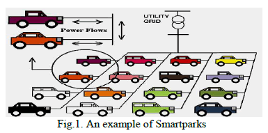
| STATCOMs can also be used for uninterrupted operation of the DFIG based wind farms in grid-connected mode during grid faults. In DFIG-based wind turbines to block the rotor side converter (RSC) during the fault and to shortcircuit the rotor terminals with a crowbar. During that period, the wind turbine generator behaves as a squirrel cage induction generator and absorbs reactive power. One way to supply this reactive power is to set the grid-side converter (GSC) to reactive power and voltage control mode during that period. However, if the network is weak, the reactive power supplied by the GSC may not be sufficient. Hence, additional reactive power support from STATCOM-like devices is necessary. In this paper, instead of a STATCOM, similar performance has been achieved from SmartParks when they are used as virtual STATCOMs in coordination with the GSC of a 400 MW wind farm in a 12-bus system. Fig. 1 shows an example of Smartparks. |
 |
DEVELOPMENT OF SMARTPARK MODEL |
| In order to develop a SmartPark model and to utilize it as a virtual STATCOM, it is essential to realistically assess the P-Q capability of an individual PEV. To obtain that capability curve, the PEV is represented by a dc voltage source, followed by a bidirectional three-phase inverter, as shown in Fig.2. |
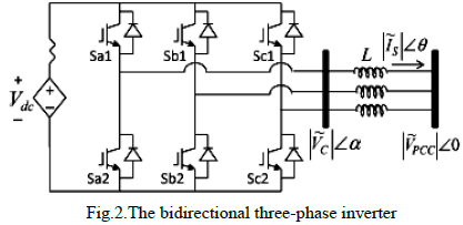 |
| The dc source is considered ideal. The value of series resistance is 0.005ohm. The inverter generates a 208V threephase line-to-line rms voltage, which then passes through a transformer to connect to the utility. Between the inverter and the transformer, there is a small inductance. The control strategy for the vehicle inverters is presented in Fig. 3 The active and reactive powers at the output of the inverter in the d-q reference frame are expressed as |
 |
| In a synchronously rotating reference frame, the peak line-to neutral voltage lies on the q-axis, and vds=0. Therefore, the objective of the control is to command the currents corresponding to the demanded power, as follows: |
 |
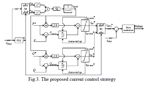 |
| The first component on the right-hand side of (3), (4) is based on the power equations (1), (2), where vpeak is the filtered line-to-neutral peak voltage. The control action is essentially a summation of an integral control and a nonlinear feed forward path. The q-axis and d-axis commanded currents are then transformed into a-b-c reference frame, and the switching pulses are generated by delta current-regulation. However, if the iqs* or ids* hits the upper limit and the error is still positive, the error accumulates through the integrator. Then, when the control action is supposed to reduce, this accumulated error prevents it from coming down to the desired value. This creates an overshoot and delays settling. In order to solve this problem, an anti-windup strategy is used. A thorough investigation of different anti-windup strategies is beyond the scope of this paper. |
 |
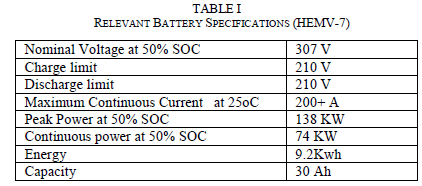
| With this control, the P-Q capability of a realistic vehicle battery is now studied. Since battery capacity and specific energy increase every year, and the V2G transaction is a futuristic scenario, it is better to study the P-Q capability of a realistic battery with high power and high specific energy.An Li-ion battery system used for hybrid electric military vehicles (HEMV-7) is therefore considered for this study. Its nominal voltage at 50% SOC is 307 V. The Li-ion battery system is obtained by packaging 5 to 8 modules of 12 cells 34 P Li-ion cells. The relevant specifications of that battery system are presented in Table I |
 |
MODELING THE TEST SYSTEM |
| Modeling the Overall System |
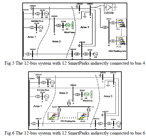
| The test system considered in this paper is a standard 12-bus power system originally proposed to evaluate the effects of FACTS devices in the transmission level. The system has four generators and three interconnected areas. Generator G1 represents the infinite bus (Fig. 5). In this study, a 400MW wind farm replaces generator G4. In order to have a significant reactive power compensation capability that matches the system’s requirements during voltage control,12 SmartParks (PL1 to PL12) with equal ratings, as mentioned in the previous section, are integrated to the system. Previous studies have shown that in the 12-bus system, bus 4 in Area-3 has the lowest voltage under normal conditions. Therefore, in the case study, SmartParks are indirectly connected to bus 4 in order to compare their voltage control capability with that of a STATCOM. The SmartParks are connected directly to bus 13, an additional bus added to the original 12-bus system in order to connect the SmartParks bus13 is connected to bus 4 through 22.9 kV/230 kV step-up transformers. |
 |
| B. Modeling the Wind Farm |
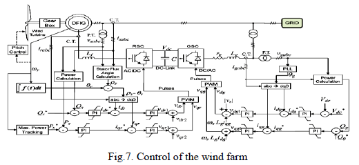
| The wind farm is equipped with a Doubly Fed Induction Generator. It uses back-to-back PWM converters for variable speed wind power generation. The control objective of the grid-side converter is to keep the dc link voltage constant regardless of the magnitude and direction of the rotor power. A stator-oriented vector control approach is used where the direct axis current controls the dc link voltage and the quadrature axis current controls the reactive power, and, in turn, the voltage at the point of common coupling. The only difference is that an additional PI controller is used to generate the reactive power command for the grid-side converter from the voltage error signal. The objective of the rotor-side converter is to control the active and reactive power from the stator. This is achieved by putting the d-axis of the rotor reference frame along the stator flux vector. The q-axis current reference is generated directly from the commanded electrical power, and the d-axis current reference is generated from the commanded stator reactive power. The electrical power command is generated from the optimum operating point-tracking strategy, when the wind speed is below a certain value. The pitch control does not work at that time, and the wind turbine captures the maximum possible energy at that wind speed. However, if the wind speed exceeds a certain value, the pitch control limits the power generated by the wind turbine. All the symbols used in Fig. 6, which presents the schematic diagram of the control strategy, carry their usual meanings. |
 |
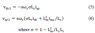
| The compensation terms for the rotor-side converter in Fig. 6 (vdr2 and vqr2) are expressed as follows: |
 |
| C. Modeling the Wind Farm |
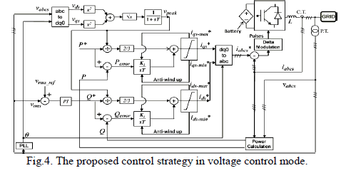
| In order to compare the performance of the STATCOM with 12 SmartParks of ±25 MVAR capacity, a 300 MVAR STATCOM is considered. The switch in Fig. 4 can toggle between the two positions to connect either the STATCOM or the SmartPark bus (bus 13) to bus 4. The STATCOM is used in voltage control mode with a control strategy. One PI controller generates the d–axis current reference while maintaining the dc-bus voltage of the STATCOM at a constant value, and the other PI controller generates the q-axis current reference with an objective to maintain the voltage at bus 4 at a desired level. The other two PI controllers keep track of the reference currents, and their outputs are added to the cross coupling compensation terms to produce d and q-axis commanded voltages. Those voltages are converted to an ab- c reference frame, and the pulses are generated by sine-triangle modulation. |
COORDINATED REACTIVE POWER CONTROL STRATEGY |
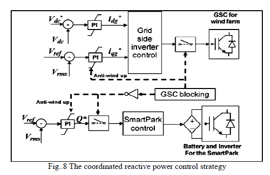
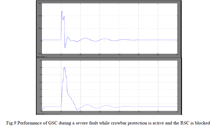
| The current in 1 the GSC current from reaching such a high value, it can also be blocked at the same time with the RSC SmartParks should be coordinated with the GSC as follows: when crowbar protection is active and both the RSC and GSC are blocked, the SmartParks should be switched to voltage control mode. As soon as crowbar protection is deactivated (after a small time delay of five cycles from the instant of fault clearance) and the RSC and GSC restart switching, the task of voltage control should be switched from the SmartParks to the GSC. In the presence of external reactive compensation, it is not necessary for the GSC to restart switching simultaneously with the RSC. It can be delayed for a short period of time. Realistically, SmartParks can satisfy the very limited duration for which this external reactive power compensation is demanded for this strategy. The schematic diagram for this coordinated control is shown in Fig. 6. The two integrators, one which generates the q-axis current command for the GSC and the other which generates the reactive power command for the SmartParks from the bus voltage deviation, should be reset while the respective controllers are not active to prevent integrator windup, as shown in Fig. 6. |
 |
 |
SIMULATION RESULTS |
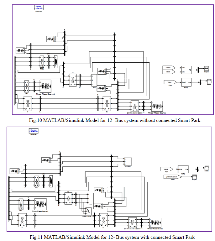
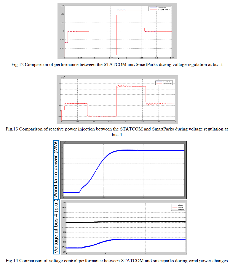
| . In regards to SmartParks, a case study is presented. In the case study, the performance of the SmartParks in voltage control mode is compared with a STATCOM when it is connected to bus 4 (Fig. 5). Without any reactive power compensation, the nominal voltage at bus 4 is 0.974 p.u. In order to establish that the SmartParks can behave like a virtual STATCOM, the voltage at bus 4 is commanded from its nominal value to 1.0 p.u. From 1.0 p.u., it is then commanded to 0.95 p.u., from 0.95 p.u. to 1.05 p.u., and then finally back to 1.0 p.u. A similar experiment was carried out with a 300 MVAR STATCOM, and these two performances are compared. Fig. 12 shows that SmartParks behave exactly like the actual STATCOM for the entire range of the permissible bus 4 voltage. Fig. 13 compares the reactive power injection from the STATCOM and from the 12 SmartParks. The same amount of reactive power was injected or absorbed during the voltage regulation study. Next, an experiment was carried out to study the impact of wind speed variation on the system and to observe how the SmartParks respond to the situation. Initially, it is assumed that the wind speed is 10 m/s; at that speed, the wind farm generates 190 MW. At this point, the voltage at bus 4 is 0.974 p.u. without any reactive power compensation.Fig.10 and Fig11 shows MATLAB/Simulink models for 12- Bus system without connected Smart Park and with connected Smart Park respectively. |
 |
| With the SmartParks in voltage control mode, that voltage can easily be regulated to 1.0 p.u. as before. Now, suddenly, the wind speed changes from 10 m/s to 12 m/s, which changes the wind power generation to 350 MW. Without any voltage regulation, this change in wind power moves the entire system to a new operating point where voltage at bus 4 also changes to 0.983 p.u., as shown in fig. However, with the STATCOM or the SmartParks in voltage control mode, at both of these operating points, the voltage at bus 4 can be maintained successfully at 1.0 p.u., as shown in Fig. 11. |
 |
CONCLUSION |
| An intelligent idea to exploit the reactive power capabilities of a large number of plug-in vehicles in SmartParks and utilizing the aggregation as a virtual STATCOM has been presented in this paper. From there, an aggregated SmartPark model is developed using MATLAB/Simulink software. The SmartParks performance is compared with that of an actual STATCOM under various contingencies. Finally, a coordinated reactive power support strategy between the SmartParks and the grid-side converter of the wind farm is presented to improve the fault-ride-through capability of the wind farm while maintaining the continuity of service and without violating the grid-side reactive power and current limits. |
ACKNOWLEDGMENT |
| Our thanks to the experts who have contributed towards development of the template. |
References |
|