ISSN ONLINE(2278-8875) PRINT (2320-3765)
ISSN ONLINE(2278-8875) PRINT (2320-3765)
| Rajesh Kr Ahuja, Sushil Verma, Bhupender Dhull Department of Electrical Engineering, YMCA University of Science & Technology, Faridabad, Haryana,India |
| Related article at Pubmed, Scholar Google |
Visit for more related articles at International Journal of Advanced Research in Electrical, Electronics and Instrumentation Engineering
This paper presents a simulation of a simple control scheme for a three-phase shunt active filter to remove harmonics and reactive power compensation of the non-linear loads. A 3-phase voltage source inverter bridge with a dc bus capacitor is used there as an active filter (AF). A PWM current control is used to generate the gating signals to the AF. Source reference currents are calculated from load currents, dc bus voltage and source voltage. The command currents for AF are calculated using source reference currents and load currents. A three- phase diode rectifier with resistive loading is used as non-linear load. The validity of scheme is shown by simulation results.
Keywords |
| Active Filter (AF), Pulse Width Modulation(PWM), Total Harmonic Distortion(THD) |
INTRODUCTION |
| In recent years both power engineers and consumers have been giving focus on the “electrical power quality” i.e. degradation of voltage and current due to harmonics, low power factor etc. Nearly two decades ago majority loads used by the consumers are passive and linear in nature, with a few non-linear loads thus having less impact on the power system. Solid state power converters are widely used in applications such as adjustable speed drives (ASD), static power supplies and asynchronous ac-dc links in wind and wave generating systems. These power converters behave as non-linear loads to ac mains and inject harmonics and result in lower power-factor and efficiency of the power system. However, due to technical advancement in semiconductor devices and easy controllability of electrical power, nonlinear loads such as SMPS, rectifier, chopper etc. are more used. |
| The power handling capacity of modern power electronics devices such as power diode, silicon controlled rectifier (SCR), Insulated gate bipolar transistor (IGBT), Metal oxide semiconductor field effect transistor (MOSFET) are very large, so the application of such semiconductor devices is very popular in industry as well as in domestic purpose. Whilst these advantages are certainly good but there lies of such excessive use of power electronic devices a great problem, i.e. generation of current harmonics and reactive power in the power system network. As a result, the voltage at different buses of power system network is getting distorted and the utilities connected to these buses are not operated as designed. |
| The harmonic current pollute the power system causing problems such as transformer overheating, voltage quality degradation, rotary machine vibration, destruction of electric power components and malfunctioning of medical facilities etc. Conventionally, passive filters were the choice for the elimination of harmonics and to improve powerfactor. These passive filters have the disadvantages of large size, resonance, and fixed compensation. In the last couple of decades, the concept of active filters (AF) has been introduced and many publications have appeared on this subject [5-7]. Many control concepts, such as instantaneous power theory [1,2] notch filters [3], and flux based controllers [4] have also been introduced. Most of these control schemes require various transformations and are difficult to implement. This paper presents a simple algorithm to achieve the control for AF. To provide clean power at the consumer-end active filter (AF) is used. Several approaches, such as, hybrid filters and multistep inverters are reported to reduce the size of active filters [8]. In AF, the main objective is to maintain sinusoidal unity power-factor supply currents (by shunt AF) to feed active power to the load and to meet the losses in the AF. These two components of active power can be computed from load currents, dc bus voltage and supply voltages. From the measured active power required by the system, reference unity power-factor supply currents are derived. By subtracting load currents from these reference supply currents, compensating currents of the AF phases are obtained. The study is based on a 3-wire 3-phase system. The familiar 3-phase uncontrolled rectifier with resistive loading is taken as a non-linear load. The steady state and transient performance of the proposed control scheme is found quite satisfactory to eliminate the harmonics and reactive power components from utility currents. |
SYSTEM CONFIGURATION |
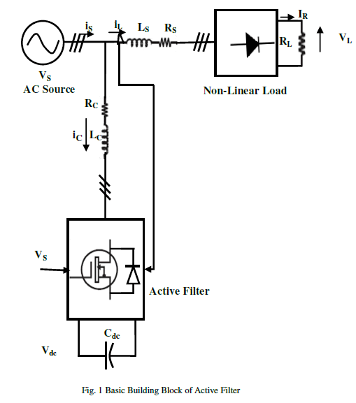
| The basic system blocks of the conventional parallel AF are shown in Fig. 1. The AF is composed of a standard 3- phase voltage source inverter bridge with a dc bus capacitor to provide an effective current control. A PWM current control is used to provide quick response of the AF. The non-linear load is a dc resistive load supplied by 3-phase uncontrolled bridge rectifier with an input impedance and resistor on the output. Because of resistive loading the uncontrolled bridge rectifier draws pulsating non sinusoidal currents from ac source. It also draws reactive power from the mains depending upon the load magnitude and its parameters. |
| The basic function of the proposed control scheme of parallel AF is to compensate harmonics and the reactive power needed for the load so that the ac supply give only the sinusoidal balanced unity power factor currents. The desired AF currents are calculated by sensing the dc bus voltage, load current and source voltage. The PWM current controller generates the switching signals to AF devices to force the desired currents into the AF phases. With this control scheme, the AF meets harmonic and reactive current requirements of the load. The AF connected in parallel with the load, also enhances the system efficiency as the source does not process harmonic and reactive power. The active filter (AF) is a popular approach for cancelling the harmonics in power system. The main component in the AF is the control unit. |
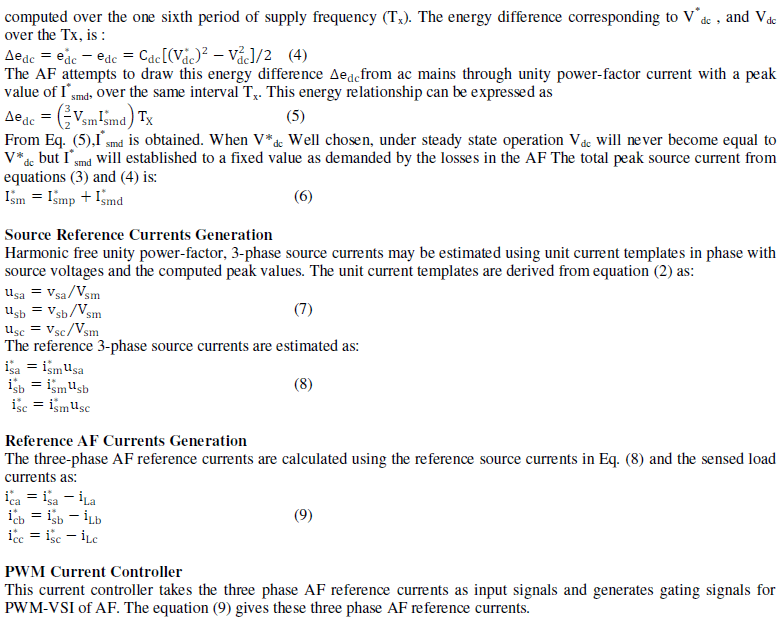
| Fig. 2 shows the proposed control scheme of the shunt AF [5]. The ac source supplies the fundamental active power component of load currents and another fundamental component current is to maintain the voltage across capacitor to a desired value. The later component of source current is to feed the losses in the converter such as switching loss, ohmic loss, capacitor leakage loss, etc. in the steady state and to maintain the stored energy on the dc bus during transient conditions such as sudden fluctuations of load etc. This component of source current (I* smd) is computed using dc bus capacitor value (Cdc,), average voltage on dc bus (Vdc) and a chosen reference voltage of the dc bus (V* dc). The fundamental active power component of the load currents (I* smp) is computed using sensed load currents and voltages. The total reference source peak current (I* sm) is computed by taking sum of components (I* smp) and (I* smd). The instantaneous source reference currents (i* sa, i* sb and i* sc) are computed using the peak value (I* sm) of current and unit current templates (usa,usb and usc) derived from sensed source voltages. The command currents of the AF (i* ca, i* cb and i* cc) are computed by taking the difference between instantaneous source reference currents (i* sa, i* sb and i* sc) and sensed load currents (iLa, iLb and iLc). |
| The PWM current controller is used over the reference AF currents (i* ca, i* cb and i* cc) to obtain the gating signals to the devices of the AF. On the basis of proper shaping of compensating currents the value of AF inductance (Lc) is selected. With high value of Lc compensating currents do not track reference currents and low values of Lc will produce large ripples in compensating currents. The AF meets the requirements of harmonic and reactive components of load currents locally, resulting in sinusoidal unity power factor source currents under fluctuating conditions of load in the system. |
| The system consists of ac source, non-linear load, the AF and the simple control scheme. The components of the system are analysed separately and integrated for development of the complete model for the simulation. |
Control Scheme |
| The operation of the control scheme has been explained in the previous section. The governing equations for the different blocks are deduced in sequence. |
 |
Peak Source Current Estimation |
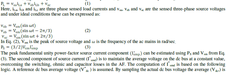
| The peak source current (I* sm) has two components estimated as follows. The source active component corresponding to the load (I* smp) is computed from the average load power (PS). The instantaneous power PL is, |
 |
 |
PERFORMANCE OF SYSTEM |
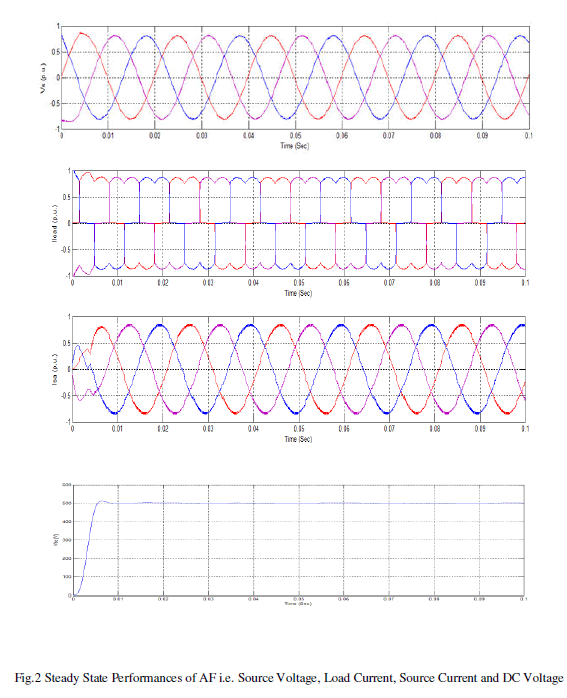
| Performance characteristics of the AF system with proposed control scheme are given in Figs. 2-4 illustrating the steady state and transient behaviour at different loads. Fig. 2 shows the source voltage, three-phase source currents, load current and dc bus voltage when a load of 10 ohm is used across rectifier diode. |
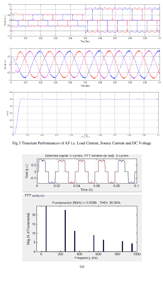
| In steady state condition the simulation time is taken as t=0 to t=0.1 sec with constant load. The load current and source current is shown in Fig. 2.The AF inject the compensating current in system, which results in compensation of source current. The compensating current containing only the harmonic current, which is introduced to the power system due to non-linear load but in opposite phase. It is clear from the Fig. 2 that, the waveform is sinusoidal with some high frequency ripples. The DC voltage across capacitor is also shown in Fig. 2.For transient state, during the period t=0 to t=0.05 sec Rs parameter of the nonlinear load is set as 15 Ω. From t=0.05 to 0.1 sec the load parameter is changed to 7.5 Ω. The corresponding load current and source current waveforms obtained are shown in the Fig. 3. Fig. 3 indicates that after 0.05 sec the load current magnitude is changing as the load is changing and settling very quickly. The AF supplies the compensating current for source current compensation. The capacitor voltage during transient period is nearly same as the steady period is shown in Fig. 3. |
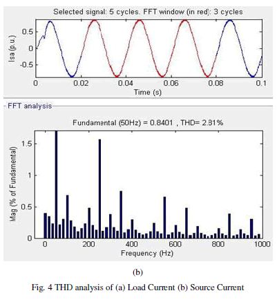
| Fig. 4 shows the THD analysis of load current and source current. Simulations of integrated control circuit of AF are conducted with steady state and transient conditions. The results obtained show that the source current has minimised harmonics with shunt AF. THD analysis shows that PWM current controller has good performance for reduction of harmonics. FFT analysis of the active filter calculated the THD of the load current and source current. Here THD of source current has minimized to 2.81% which is less than 5% |
 |
 |
 |
CONCLUSION |
| In this paper, the performance of the shunt active filter is analysed by simulation in MATLAB/Simulink using a simple technique for minimizing harmonics and compensating reactive power in the power system. The performances of shunt active power filter with PWM Current Controller are verified with the simulation results. From the results; it clearly indicates that, the current ripple is less by using PWM Current Controller. The transient response and steady state performance of this controller has been evaluated. The THD of the source current after compensation is 2.81% with PWM Current Controller which is less than 5 % proving the validity of scheme. |
References |
|