ISSN ONLINE(2278-8875) PRINT (2320-3765)
ISSN ONLINE(2278-8875) PRINT (2320-3765)
| Vivek M. Nangare1, Krushna A. Munde 2 M.E. Students, MBES College of Engineering, Ambajogai, India |
| Related article at Pubmed, Scholar Google |
Visit for more related articles at International Journal of Advanced Research in Electrical, Electronics and Instrumentation Engineering
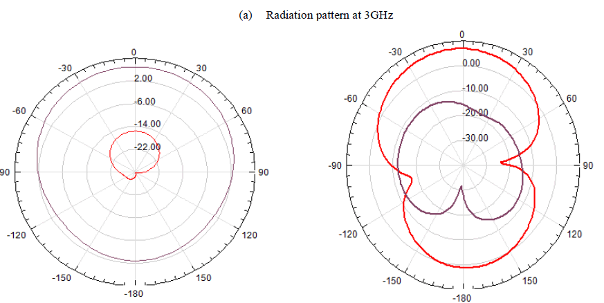
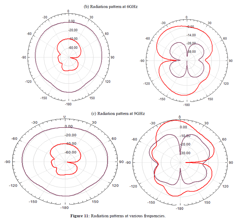
In this paper, a printed, compact & ultrawideband (UWB) antenna used for three band notch characteristics are reported. Ultra-wideband (UWB) is one of the recent topics that received a great concern from academic and industry. However, UWB found many difficulties to be standardized due to the overlay working that made UWB an important potential interference source to many licensed and unlicensed spectrum throughout the band 3.1-to-10.6 GHz. In this paper we propose a compact ultra-wideband microstrip antenna with triple band notched 3.5 GHz, 4.9 GHz and 9.3 GHz. The proposed antenna consists of a curved patch with a partial ground plane that is fed by 50 Ω microstrip line. In this antenna notch filter achieved using small rectangular metallic strip with different size and positions. The notch frequency can be obtained by varying the length of rectangular metallic strip. Moreover, the proposed antenna provides good radiation patterns across the working bands and a relatively flat gain over the entire frequency band excluding the rejected bands.
Keywords |
| Ultrawideband antenna, Rectangular metallic strip, VSWR, Partial ground plane. |
INTRODUCTION |
| Since the U.S. Federal Communication Commission (FCC) authorized the unlicensed use of the ultrawideband (UWB) in (3.1-10.6 GHz) in February 2002, significant research activities and interests have been increased in academic and industrial fields recently to explore various UWB antennas [1]. There are many design challenges in design of ultrawideband (UWB) antenna some of them are radiation stability, compact size, low manufacturing cost & electromagnetic interference. The frequency range for UWB systems approved by the FCC between 3.1 to 10.6 GHz will cause interference to the existing wireless communication systems, such as the IEEE 802.16 WiMAX system at 3.5 GHz (3.3-3.7 GHz) and the IEEE 802.11a wireless local area network (WLAN) system at 5.2/5.8 GHz (5.15-5.825 GHz) [2]. To avoid interference from coexisting system it is highly desirable to introduce notch filter internally or externally. By introducing the notch filter internally we can minimize the required space and cost rather than adding externally. |
| There are many methods used in literature to introduce notch filter in UWB antenna. Some of them notched band antennas are introduced in literature [3-16]. In this circular notch antenna, with fractal tuning stub and ground slot plane with this type of structure one can achieve the notch filer. Rather using some C, H, and L shaped slots some of the literatures used complementary split ring resonator (CSRR), complementary spiral loop resonator (CSLR) and in addition of parasitic elements for notch band filter design. By adjusting the slot dimensions resonance frequency is achieved. These methods are not useful to avoid lower WLAN frequency successfully. The above methods can change the antenna design and its characteristics. So the literature gives method to notch band filter is capacitively loaded loop resonator (CLL) without changing antenna design. Each CLL element is having high quality factor and compact size. But it is difficult to put these CLL elements in the slot of antenna itself. The area required for each CLL element may vary with frequency. |
| In this, compact UWB antennas are presented. Each UWB antenna is having the size of 34mm×27mm×0.787mm. The antenna is notched by using metallic strips. These metallic strips are simple in design and compact in sizes. By adjusting the width and position of metallic strips the notch frequency can be varied. The antenna is simulated using Ansoft HFSS v.13. |
ANTENNA GEOMETRY WITH AND WITHOUT NOTCH FREQUENCY |
A. UWB antenna |
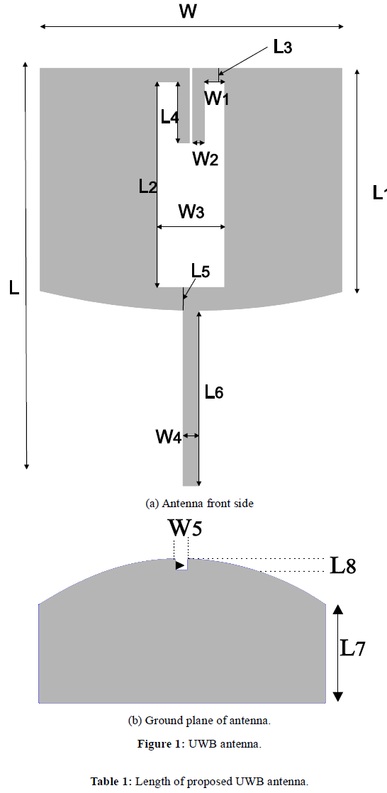
| Figure 1(a), (b) shows the basic geometry of proposed antenna for UWB operation. Substrate used for the design is RT/duroid 5880 with dielectric constant of 2.2, and which has the height of 0.787mm. All the parameters of the geometry are indicated in Figure 1 (a), (b). The overall size of antenna is 34mm×27mm×0.787mm. Parameters of the proposed geometry are listed in Table 1 and Table 2. |
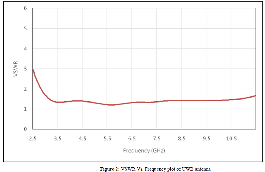
| Length and width parameters required for design of microstrip antenna. This antenna is having VSWR of less than or equal to 2 for entire frequency range 3.1 to 10.6 GHz as shown in Figure 2. |
 |
 |
 |
B. Single notch UWB antenna |
| In order to notch single frequency of the antenna the metallic strip is connected & touched to microstrip feed line of the antenna as showed in Figure 3. This metallic strip provides the resonance required to notch the antenna. |
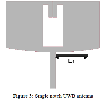 |
| This metallic strip is having the dimensions L1=12, W=0.1 at position X=19.6, Y=14.7, Z=0.787. |
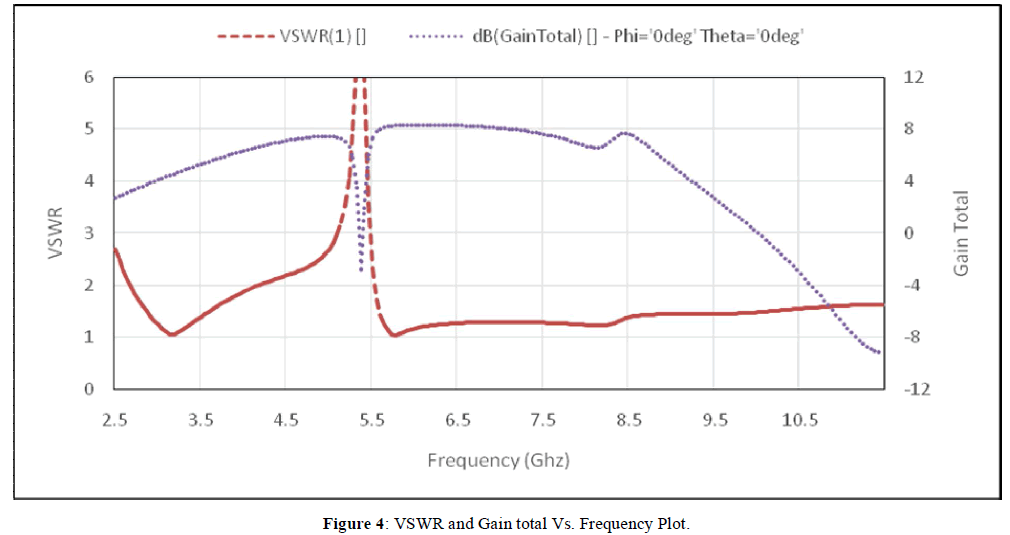 |
| From Figure 4 we can observe that the notch frequency is obtained at 5.4GHz by using the single strip in antenna design. |
C. Effect of L1: |
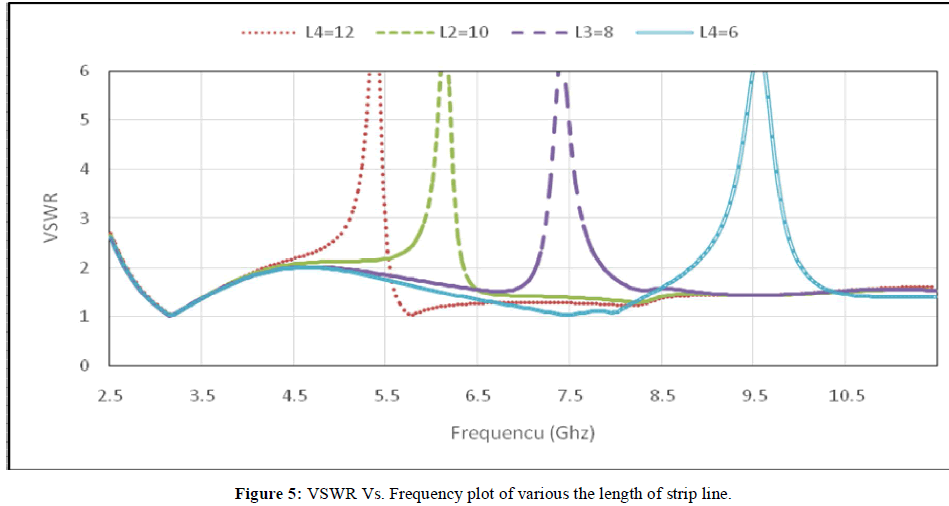
| Metallic strip is showed in Figure 3. The length of this metallic strip is changed from 12mm to 6mm in steps of 2mm keeping all the parameters constant. VSWR characteristics of these changes are given in Figure 5 and its effects are presented in Table 3. From this study it can be noted that the notched frequency is shifted towards right as the value of length changes. |
 |
D. Effect of width: |
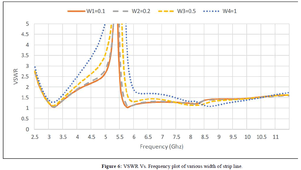
| Metallic strip is showed in Figure 3. The width of this metallic strip is changed from 0.1mm to 1mm in random steps as all the parameters constant. VSWR characteristics of these changes are given in Figure 6 and its effects are presented in Table 3. From this study it can be noted that the notched frequency is broadened as the value of width changes. |
 |
| The notch should be at desired frequency band only. So from this there is no need to change the dimension of UWB antenna to obtain notch band. By simply adjusting the length of strip line one can obtain desired notch frequency. The parametric study gives out approximate predicted relation in between length of strip to lower frequency of notch band. |
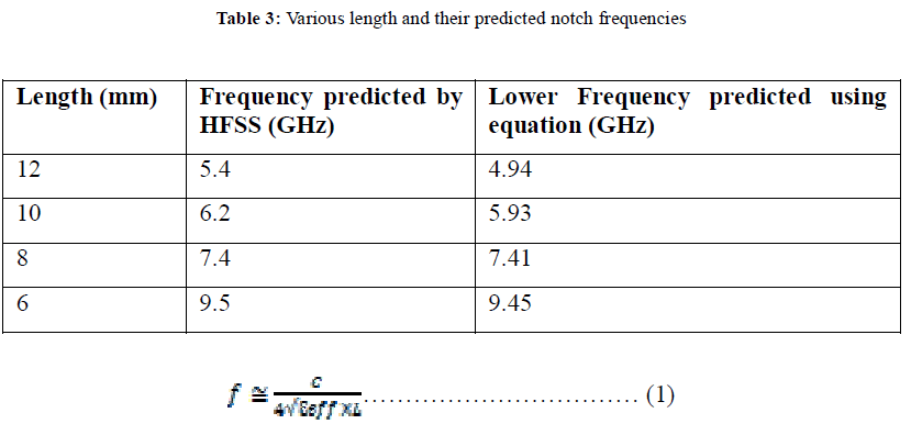 |
| Where L is the total length of strip line, C is the speed of light and εeffis effective dielectric constant. This equation is quite useful for single strip notch frequency antenna design. |
E. Dual band notch UWB antenna |
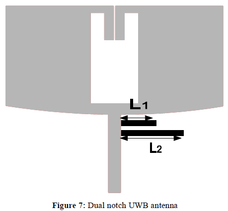
| For designing dual band notch filter one can achieve using same structure operated in single notch by adding a metal strip. In proposed dual notch antenna two different length strips are added in UWB structure. This gives the different notch frequencies. The proposed antenna shown in Figure 7. |
 |
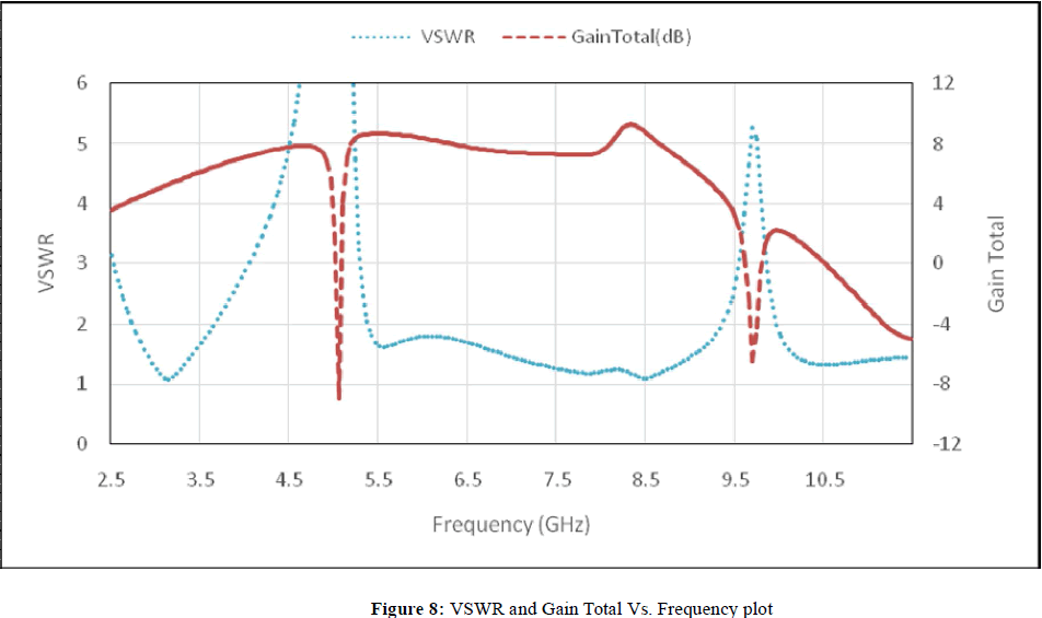 |
| This antenna consist of two metallic strips of L1= 6, L2=11 placed at X1=19.6, Y1=14.7, Z1=0.787 and X2= 20.6, Y2=14.7, Z2=0.787 respectively. In this width is fixed at 0.1mm.The obtained notch frequencies are 5.1 and 9.6. By changing the dimensions of metallic strips notch frequency can be changed. |
F. Tri-band notch UWB antenna |
| Just like single, dual notch antenna designs tri-band notch antenna designed using calculating different metallic strip lengths. In this proposed antenna design four metallic strips are used for design of tri band notch antenna. Two strips are used for notching two bands of antenna. Other two strips are symmetrical and used for notching single frequency band. These band notch frequencies are different from single and dual notch frequency bands. The tri-band notch antenna proposed in Figure 9. |
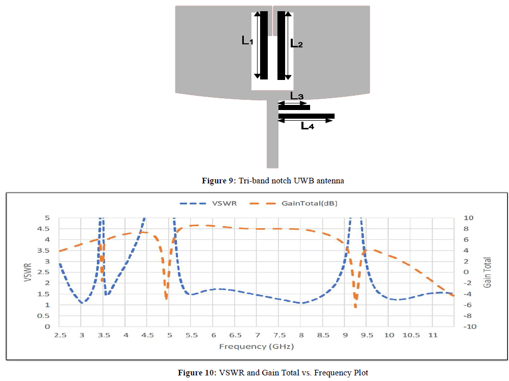 |
| In this proposed antenna the two metallic strips are placed at X3=19.9, Y3=14.7, Z3=0.787 and X4=20.6, Y4= 14.7, Z4=0.787 which having lengths of L3=6mm and L4=11.5 mm respectively. These two strips produce notch frequencies of 4.5 GHz and 9.2 GHz. The other two strips are placed at X1=1, Y1=12.3, Z1=0.787 and X2=1, Y2=14.7, Z2=0.787 which having lengths 16.4mm for each of them. These two strips produce a single notch frequency of 3.5 GHz because these two strips are symmetric to each other. In this proposed design width of strip lines are fixed at 0.1mm. The VSWR and Gain characteristics are shown in Figure 10 which shows the notch frequencies are at 3.5, 4.9 and 9.3. |
 |
 |
CONCLUSIONS |
| A compact and printed three notch UWB antenna has been presented. The antenna is operated in frequency range of 3.1 GHz to 10.6GHz. Simple metallic strips are connected and touched front side of antenna to obtain notch band as well as gives flat gain performance in operating bands. By simply adjusting the dimensions of metallic strip lines desired notch frequency can be obtained. The metallic strips are used either in simple or symmetric case. High gain and desired notch frequency verified by using HFSS simulator. |
References |
|