ISSN ONLINE(2278-8875) PRINT (2320-3765)
ISSN ONLINE(2278-8875) PRINT (2320-3765)
Neethu Salim1, Benny Cherian2, Geethu James3
|
| Related article at Pubmed, Scholar Google |
Visit for more related articles at International Journal of Advanced Research in Electrical, Electronics and Instrumentation Engineering
Induction heating applications require high frequency currents which are obtained using resonant converters viz., Series and Parallel resonant inverters. The resonance frequency in these converters will be tuned to a high value. A single-switch parallel resonant converter for induction heating is discussed. Pulse width modulation (PWM) is used to control the switches. To study the performance of the topologies, simulations has been carried out in MATLAB 2010 environment. It is compared with the existing inverter topologies; half bridge and full bridge.Vienna rectifier as front end is used instead of conventional diode bridge rectifier to provide continuous sinusoidal input current at the source side with extremely low distortion. So we can improve the power factor near to unity and the total harmonic distortion can be reduced to a value below 5%. This power converter is more suitable and acceptable for cost effective high frequency (HF) consumer induction heating applications
Keywords |
| Vienna rectifier, induction heating, inverters. |
INTRODUCTION |
| Induction heating is a non-contact heating process. It uses high frequency electricity to heat materials that are electrically conductive. Since it is non-contact, the heating process does not contaminate the material being heated. It is also very efficient since the heat is actually generated inside the work-piece.This can be contrasted with other heating methods where heat is generated in a flame or heating element, which is then applied to the work-piece. For these reasons Induction heating lends itself to some unique applications in industry. Static frequency converters have been extensively applied in industry as a medium –frequency power supply for induction heating and melting installations [1]. Increasing the frequency of operation also increases switching losses and hence reduces system efficiency. One solution to this problem is to replace the "chopper" switch of a standard SMPS topology (Buck, Boost etc.) with a "resonant" switch, which uses the resonances of circuit capacitances and inductances to shape the waveform of either the current or the voltage across the switching element, such that when switching takes place, there is no current through or voltage across it, and hence no power dissipation. |
| The ordinary circuit of an AC-AC converter for induction heating typically includes a control rectifier and a frequency controlled current source or voltage source inverter [2].However, the inverting circuit is constructed by a traditional mode with four controlled switches.Inverter topologies commonly used for IH are the full-bridge and half- bridge operations. Some deviations of these topologies are used often to achieve multiple-output converters. The modulation strategies commonly applied to control output power are based on modifying either switching frequency or duty cycle to achieve the desired output power. Each power- converter topology offers different performance features with specific requirements in terms of costs, and hardware and control complexity. |
| In this paper Vienna rectifier is used instead of diode rectifier at the front end of all topologies.Traditional diode rectifiers and thyristor rectifiers draw pulsed current from the ac main, causing significant current harmonics pollution. Vienna rectifier is an excellent choice.Since by using a Vienna rectifier, THD less than 5% are obtainable with continuous sinusoidal input current and unidirectional power flow moreover any malfunction in control circuit does not manifest itself in short circuit of output or PFC front end. |
VIENNA RECTIFIER |
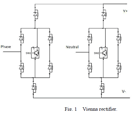
| Vienna Rectifier was originally developed at the Technical University Vienna. It comprises a semiconductor switch, say, a IGBT in each phase leg of a diode bridge. By adjusting thewidth of the pulse that turns ON the IGBT, corresponding line current is forced to be sinusoidal and in phase with the voltage. Traditional diode rectifiers and thyristor rectifiers draw pulsed current from the ac main, causing significant current harmonics pollution. The international standards presented in IEEE Std. 519 and IEEE Monitoring Electric Power Quality Std 1159-1995 imposed harmonic restrictions to modern rectifiers, which stimulated a focused research effort on the topic of unity power factor rectifiers. Vienna rectifier is an excellent choice now a days since by using a Vienna rectifier sinusoidal input currents with Power Factor equal to unity, THD less than 5% with sinusoidal input current and unidirectional power flow moreover any malfunction in control circuit does not manifest itself in short circuit of output or PFC front end. Fig. 1 represents Vienna rectifier configuration for a single phase source. A simple carrier based PWM is used at supply frequency to provide the switching instance for the Vienna rectifier. The switches SW1 and SW2 are complementary to each other. |
 |
HALF BRIDGE TOPOLOGY |
| The boost-active clamp bridge single stage high frequency inverter circuit topology includes two active power switch blocks SW1, SWs, divided series capacitors and lossless snubbing capacitor in parallel to the IH working coil. In addition, the voltage boosted block composed of the boost inductor and active power switch SW1from the circuit configuration of proposed topology. Moreover, the divided series capacitors are used to block the lower frequency current dc components flowing through the IH working coil which is assembled from the planar type litz wire |
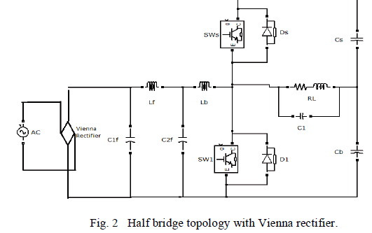 |
| The operation states are divided into six operating states during one switching period [1], which can be simply explained in the following. State 1 (SW1: ON, D1: OFF, SWs: OFF and Ds: OFF):In this operating state, two current loops are formed. The magnetic energy is stored into the boostinductorLb throughtheloopof C2f-Lb-Q1-C2f, and the input power is delivered to the induction-heated load through Cb-L0-Q1-Cb. State 2 (SW1: OFF, D1: OFF, SWs: OFF and Ds: OFF): In state 2, the resonant energy is stored into C1 through the two composed loops of Lb-C1-Cb-C2f-Lb and L0-C1- L0.State 3 (SW1: OFF, D1: OFF, SWs: OFF and Ds: ON):The energy is stored into Cs through the loop formed by Lb- Cs-Cb-C2f-Lb andtheenergyisdeliveredtothe IHloadthroughthecomposedloopof Ds-Cs-C2f-Lb. State 4 (SW1: OFF, D1: OFF, SWs: ON and Ds: OFF): In this state, the energy is delivered to the IH load throughthe composed loop of Cs-Qs- L0-Cs and the energy is stored into capacitorCb through the composed loop of Lb-L0-Cb-C2f. State 5 (SW1: OFF, D1: OFF, SWs: OFF and Ds: OFF): During this operating state, the energy is transferred to the IH load-working coil through the composed loop of L0-C1-L0 and the energy is stored into capacitorCb through the composed loop of Lb-L0- Cb-C2f as in state 4. State 6 (SW1: OFF, D1: ON, SWs: OFF and Ds: OFF): In state 6, the energy stored in the IH working coil is transferred into the capacitorCb through the composed loopof L0-Cb-L0 andtheenergyisstoredintocapacitorCb through the composed loop of Lb-L0-Cb-C2f. |
A. MATLAB SIMULINK MODEL |
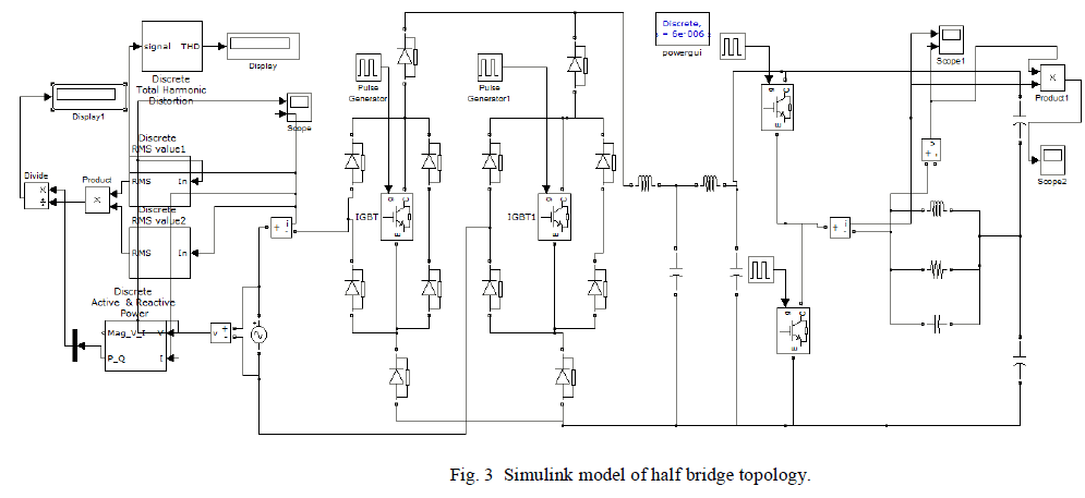
| The Simulink model of half bridge topology is given in fig.3. Input voltage of 100V is given. Switching frequency of 20 kHz is selected. Lf and Lbvalues are given as 200μH and 500μH. C1f and C2f values are 2μF and Cs, Cb are given as 3μF and 4μF. The IH coil R0, L0 are 2.5Ω and 58μH. In order to achieve a nearly unity power factor at the utility side and pure non-smoothing dc currentatinverterside,wedesignedoptimumvalueoffilterparameters. The switches are complementary to each other. |
 |
B. SIMULATION RESULT |
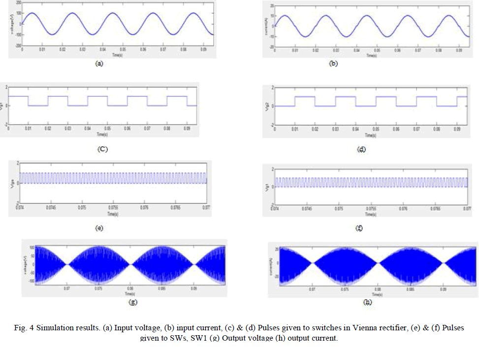
| For half bridge topology the total harmonic distortion is 3.3% by using vienna rectifier. If diode rectifier is used the THD will be more than 5%. The power factor is near to unity (0.90). Here the output power is about 2kW. |
 |
FULL BRIDGE TOPOLOGY |
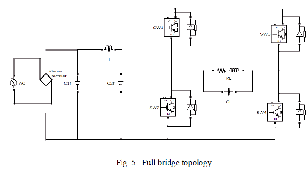
| Another commonly used inverter topology with 4 semiconductor switches is described in this section. This high frequency full bridge hybrid resonant inverter supplies more power when compared to half bridge series resonant inverter. The inverter consists of four switches SW1, SW2, SW3 and SW4 with antiparallel diodes, an induction coil that comprises a series combination of a resistor (Req) and an induction coil inductor (Lcoil). |
| In a parallel load, there would be low ON losses in the switches but turn-on / turn-off losses would be more as the switching takes place at high voltage and current [5]. So, a hybrid inverter, (i.e. by using combined series and parallel circuit) can be used to reduce the losses in the switches. Fig.5 shows a resonant inverter system for one cooking zone. Here the energy is transferred from the series resonant circuit to the parallel resonant circuit. By turning on one of the switch pairs S1, S4 or S2, S3 a resonant current starts flowing through RL to C1 and when this current is zero, the switches are turned off. After that the series resonant circuit is disconnected and the energy transferred to resonant capacitor is dissipated as heat in RL by the current flowing through the parallel resonant circuit. RL is the equivalent resistance for the magnetic loss in the induction heating system. |
 |
A. MATLAB SIMULINK MODEL |
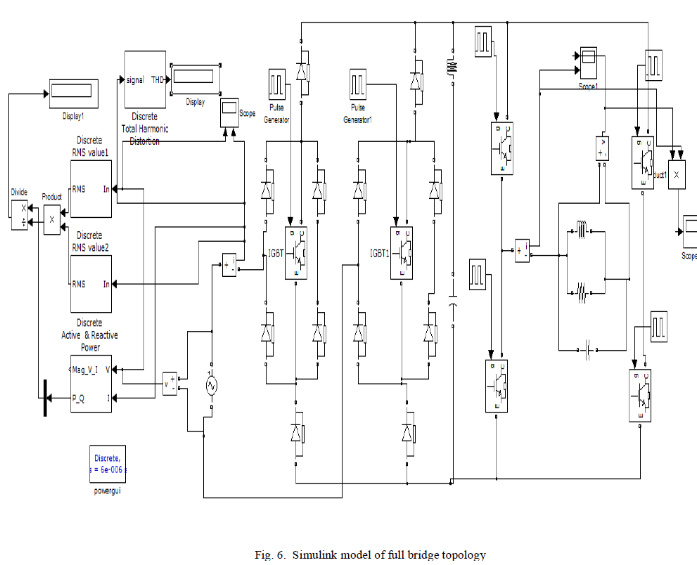
| The Simulink model of full bridge topology is given in fig.6. Input voltage of 100V is given. Switching frequency of 20 kHz is selected. Lf values is given as 200μH. C1f and C2f values are 2μF. The IH coil R0, L0 are 2.5Ω and 58μH and C1 value is given as 2μF. The switches are complementary to each other. High frequency current will get as output. |
 |
B. SIMULATION RESULTS |
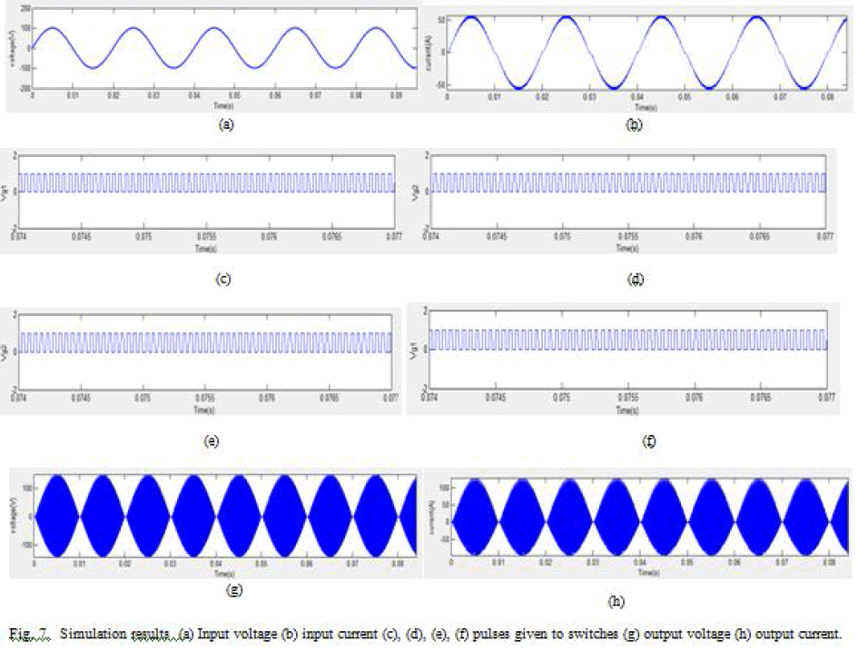
| For full bridge topology the total harmonic distortion is 3.7% by using vienna rectifier. If diode rectifier is used the THD will be more. The power factor is near to unity (0.90). Here the output power is about 3kW. |
 |
SINGLE SWITCH PARALLEL RESONANT CONVERTER TOPOLOGY |
| The inverter circuit is composed with only a single controlled switch [6], which serves as a high-frequency generator for induction heating. Fig.8 shows the circuit diagram. |
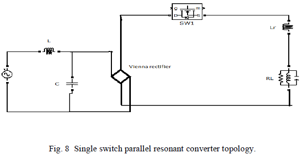 |
| First the switches in Vienna rectifier and the switch SW1 are off. In this interval the capacitor C charges up linearly at a rate and a polarity corresponding to the instantaneous input voltage. Second the switch SW1 in Vienna rectifier and the main switch are on. In this interval the capacitor C is discharging to the load. This interval ends when the capacitor voltage reduces to zero. Then all the switches are on. In this interval the current through switch flows via two parallel bridge branches. This interval ends when this switch current decreases to zero. At this moment the switch turns off and the process starts from the beginning. |
C. MATLAB SIMULINK MODEL |
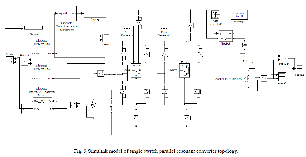
| The Simulink model of one switch topology is given in fig.9. Input voltage of 100V is given. Switching frequency of 20 kHz is selected. L value is given as 550μH. Cvalue is5μF and Lr value is 8μH. The IH coil R0, L0 are 8Ω and 100μH and C1 value is given as 2.35μF. The switches in Vienna rectifier are complementary to each other. High frequency current will get as output. |
 |
D. SIMULATION RESULTS |
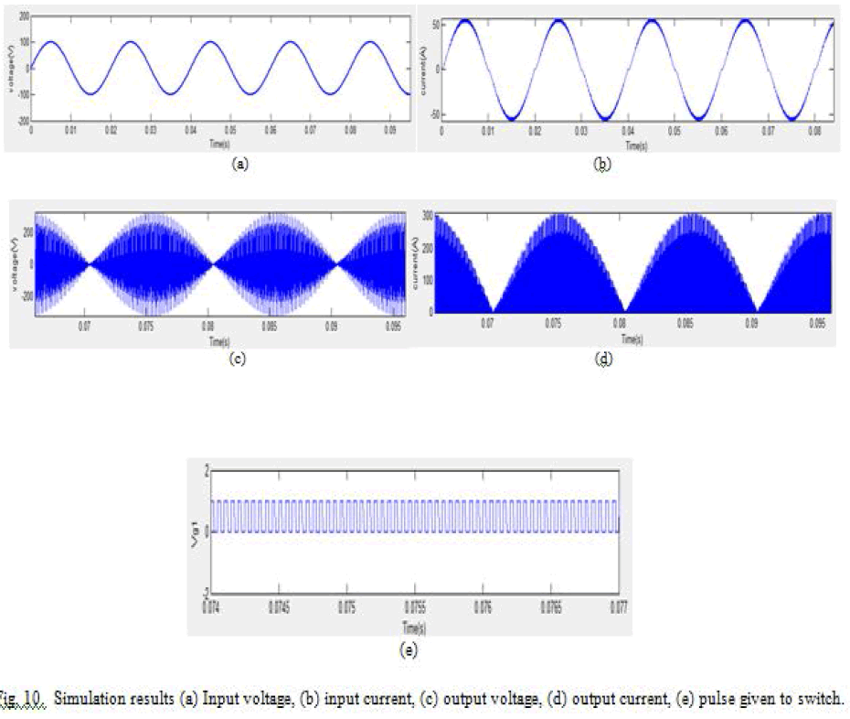
| For single switch parallel resonant converter topology the total harmonic distortion is 3.3% by using vienna rectifier. If diode rectifier is used the THD will be more. The power factor is near to unity (0.907). Here the output power is about 10kW. |
 |
CONCLUSION |
| Different inverter topologies are used in induction heating applications. Of that the basic half- bridge and full bridge inverter topologies have been compared with one switch parallel resonant converter topology. The AC-AC converter circuit for induction heating for three topologies has been simulated. Power factor is improved and it is close to unity. All the topologies had used vienna rectifier at front end. By using vienna rectifier instead diode rectifier,the THD got reduced below 5%. The circuit topology is very simple since includes only one power switch. This switch operates in a soft commutation mode. The converter provides a wide- range power control. This converter has advantages like reduced hardware, reduced stresses and high power density.The proposed topology have been done in open loop manner. It can be made closed loop using a PI controller. This can improve steady state stability. |
References |
|