ISSN ONLINE(2278-8875) PRINT (2320-3765)
ISSN ONLINE(2278-8875) PRINT (2320-3765)
Dr. RAMA RAO P.V.V.1, S.VEERABABU2, N.SARATH CHANDRA3
|
| Related article at Pubmed, Scholar Google |
Visit for more related articles at International Journal of Advanced Research in Electrical, Electronics and Instrumentation Engineering
This paper presents a single-phase multi-string multilevel inverter for micro grid applications. The multilevel topology consists of few H-bridges connected in series, each one connected to a string. The proposed multistring multilevel inverter needs only six switches whereas conventional cascaded H-bridge multilevel inverter need eight switches. The multi-string inverter topology offers advantages like quality output waveform, small LC filter size, lower total harmonics distortion (THD) and less electromagnetic interference (EMI). The results are compared between with and without pulse width modulation (PWM) technique for both the multi-string cascaded H-Bridge inverter and multi-string multilevel inverter in MATLAB/Simulink environment.
Keywords |
| Multistring Multilevel Inverters, Multistring Cascaded H-Bridge Inverter, PWM, THD, Switching losses. |
INTRODUCTION |
| Micro grid is a small scale power supply network that is designed to provide power for a small community. Both renewable and non renewable energy sources can be used in micro grid. Multistring multilevel inverters are used to obtain the sinusoidal output voltage and to reduce the total harmonic distortion by employing less number of switches. In the present scenario the distributed energy resource (DER) based single-phase inverter is usually adopted in the micro grid systems. In order to reduce conversion losses, the key is to save costs and size by removing any kind of transformer as well as reducing the power devices [1]. The microgrids are developed by using the natural resources such as photovoltaic cells and wind power generation systems etc., and have already been used as standby generation during system outages. Various inverter technologies are developed for connecting photovoltaic (PV) modules to a single-phase grid to generate power supply to a certain local area [2]. A micro grid has larger power capacity and is able to provide a coordinated integration of the increasing share of distributed generation units in the network. Micro grids are evolving as future grid systems that give environmental and economic benefits compared to expansion of modern power systems [3]. The micro grids become more prevalent and a promising solution for ever expanding electricity demand, especially in places where poor service exists by the traditional power system [4]. Multilevel inverter topology came into limelight because it can be easier to produce a required high-power, high-voltage inverter with the multilevel structures with less switching devices having low switching frequency for each switch [5]. Various topologies for multilevel inverters have been proposed in the literature. Common ones are diode-clamped, flying capacitor or multi-cell, cascaded H-bridge, and modified H-bridge multilevel [6–11]. Cascaded multilevel inverters synthesize a medium-voltage output by a series connection of power cells which use standard low-voltage component configurations. This feature gives benefit of high-quality output voltages and input currents and also outstanding availability due to their intrinsic component redundancy. Due to these features, the cascaded multilevel inverter has become a prominent alternative in the medium-voltage inverter market [12]. The modular structure of cascaded multilevel inverters simplifies the hardware implementation rather complex and also the maintenance/ operation is easier than conventional old type multilevel converters. Infact the multilevel inverters are now attractive solution in the medium-voltage and high power applications. |
| This paper proposes comparison of simulation results of a cascaded multilevel H-bridge inverter and also a multistring multilevel inverter for micro grid application without and with PWM control scheme using MATLAB/ Simulink tool. |
MULTISTRING MULTILEVEL INVERTERS |
| The block diagram of multistring multilevel inverter for microgrid application is shown in fig.1. The multi-string inverters allow the distributed energy resources (DER) to be used together in the same system – without losses in power production. This allows several DERs such as PV modules with different operating characteristics to be operated within their maximum power range, fuel cell modules etc. By doing so this not only saves space, but it also saves installation costs. There are two types inverters used in microgrid applications today: a central “string” inverter or multiple small “micro” inverters. Micro-inverters are relative newcomers to the real time applications and despite their higher cost (as much as 30% more than a central inverter) their popularity has been growing rapidly. |
 |
PWM CONTROL |
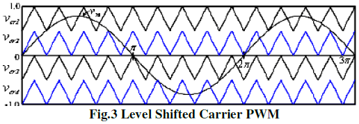
| There are two basic approaches used to generate PWM signals for multilevel inverters. The most popular PWM Techniques for CHB Inverter are Phase Shifted Carrier PWM and Level Shifted Carrier PWM shown in fig.2 and fig.3 respectively. |
 |
| In general, a multilevel inverter with m voltage levels requires (m – 1) triangular carriers. In the phase shifted multicarrier modulation, all the triangular carriers have the same frequency and the same peak-to-peak amplitude, but they differ in phase shift between the 2 adjacent carrier waves, given by . The modulating signal is usually a three-phase sinusoidal wave with adjustable amplitude and frequency, here the Phase Shift of every triangular carrier is 900. Fig.3 shows the Level shifted carrier pulse width modulation. An m-level Cascaded H-bridge inverter using level shifted modulation requires (m–1) triangular carriers, all having the same frequency and amplitude. In the Level Shifted carrier modulation, all the triangular carriers have the same frequency and the same peak-to-peak amplitude. The modulating signal is usually a three-phase sinusoidal wave with adjustable amplitude and frequency. And finally, we can get the Level Shifted Carrier waves at the Levels. |
 |
RESULTS AND DISCUSSION |
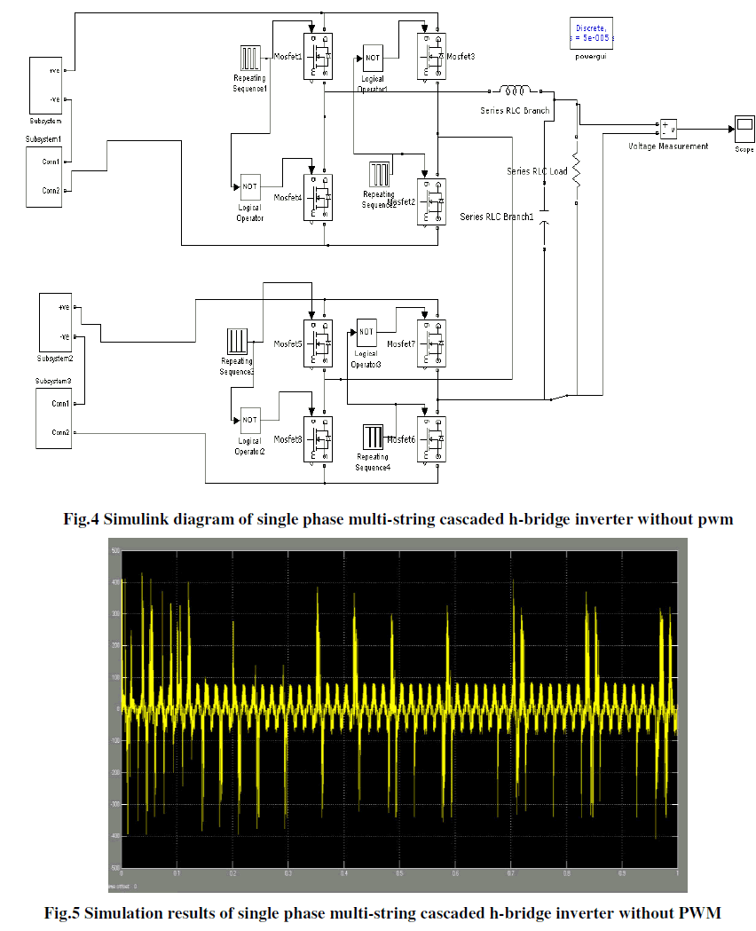
| In order to verify the effectiveness of the control strategy and modulation method, and also compensate the harmonics using PD technique the simulation software MATLAB/Simulink is used. The simulation of single phase multi-string cascaded h-bridge inverter without and with PWM technique is carried in MATLAB/ Simulink environment. Simulink diagram of single phase multi-string cascaded h-bridge inverter without pwm technique is shown in fig.4. The fig.5 shows the simulation results of single phase multi-string cascaded h-bridge inverter without PWM. |
 |
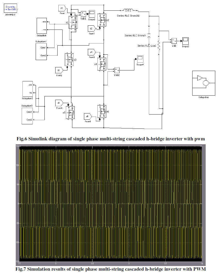
| The fig.6 shows the simulation of single phase multi-string cascaded h-bridge inverter with PWM. Fig.7 shows the simulation results of single phase multi-string cascaded h-bridge inverter with PWM. |
 |
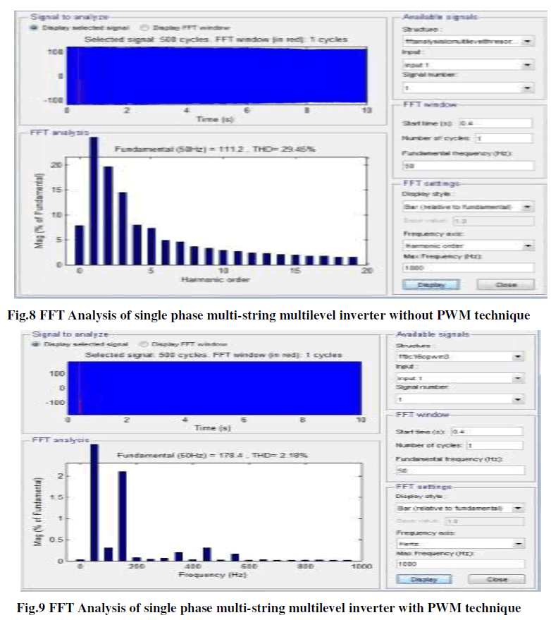
| FFT Analysis of single phase multi-string multilevel inverter without pwm technique is shown in fig.8. FFT Analysis of single phase multi-string multilevel inverter with PWM technique is shown in fig.9. The THD of single phase multi-string multilevel inverter without PWM is 28.45% which has practically observed in fig.8 whereas the THD with PWM is 2.18 %. |
 |
CONCLUSION |
| In this paper a five level multistring cascaded H-bridge and multistring multilevel inverter circuits are simulated using Simulink. The THD of the multi-string cascaded H-Bridge inverter and multi-string multilevel inverter are more reduced by applying the PWM technique and hence the stability of the systems remains stable. The switching losses are reduced by reducing the number of switches in multilevel inverter compared to cascaded H-Bridge inverter. |
| Although performance and switching losses of the multistring multilevel inverters are attractive, the future looks promising for reliable and cost effective multistring inverters that meet the practical cases. |
ACKNOWLEDGEMENT |
| We thank our Management and Principal for their extensive support to carry out our research work in the college. |
References |
|