ISSN ONLINE(2278-8875) PRINT (2320-3765)
ISSN ONLINE(2278-8875) PRINT (2320-3765)
Bijo Reji1, Arun S2, Anish Benny3
|
| Related article at Pubmed, Scholar Google |
Visit for more related articles at International Journal of Advanced Research in Electrical, Electronics and Instrumentation Engineering
In the area of distributed energy systems and industrial motor drivesmultilevel converters and inverters are the emerging trends. Single phase inverter is widely used for stand-alone systems and micro-grid application. The major limitation faced by multilevel inverters are, number of switches required large which leads to higher switching losses. A novel solar powered extended simplified multilevel inverter is proposed, in which a single phase multilevel output can be attained using less number of switches. This paper observers the feasibility of the proposed topology using Matlab/Simulink software. A seven level output voltage is obtained with less harmonic content and reduced switching losses.
Keywords |
| Simplified multilevel inverter, solar PV system, MPPT, THD |
INTRODUCTION |
| For past few years, Multi-Level Inverters (MLI) has gained attention due to wide applications in distributed power systems and electrical drives. A better sinusoidalform of ac output from dc sources like batteries, solar cells, fuel cells etc can be attained from MLIs. Such acoutput can be directly interfaced to the ac grid or aload with small filter circuit in its output. |
| A staircase waveform can synthesize from multiple DC input sources fed to a MLI. MLI’s stepped waveform depicts a better harmonic profile. The unwanted harmonics result in problems such as the electromagnetic interference, current pulsation, and additional power loss and may cause equipment damage. Renewable sources can be connected to the ac grid with the help this MLIs, where high quality AC waveforms is essential. In other applications such as AC motor drives, the low-order harmonics are the main issue. The unwanted output harmonic contents can be considerably reduced by using Pulse Width Modulation (PWM) control techniques applied to the inverter switches. |
| The major limitations of MLIs are requirement of large number of power switching devices and associated gate driver circuits. The number increases with increase in number of output levels. Such system will be expensive and complex. Therefore, practical implementation of MLI requires minimizednumber of switches and gate driver circuits, without reducing its output aclevel. |
MULTILEVEL INVERTER TOPOLOGIES |
| Following are the basically used MLI topologies to attain multilevel ac output for electrical drive and power engineering applications[1]-[3]. |
A. Diode clamped MLI |
| In diode clamped MLI proposed by Nabaeet al.,intermediate voltage levels are attained with the help of capacitors and clamp diodes. Then the voltage across switch becomes half of the input dc voltage, for a three level inverter. This MLI are limited due to its capacitor voltage balancing problems and not suitable for solar (Photo-Voltaic) PV applications. |
B. Flying Capacitor MLI |
| In this MLI, clamping voltages and multileveloutput are achieved by floating capacitors and switches. Redundant switching states can be achieved without additional clamping diodes, which are used balance the capacitor charge, evenunder loaded condition and obtain required dc level. As the number of output level increases, number of capacitors also increased.` |
C. Cascaded H-bridge MLI |
| In cascade H-bridge topology, the multilevel output can be achieved with symmetrical or asymmetrical dc voltage sources with comparatively less number of switches. Addition or subtraction of dc sources can be achieved easily, which in turn increase the number of levels in output waveform. But for each level addition, four controllable switches and additional control circuits are required. |
D. Modular MLI (half H-bridge) |
| Modular MLI is deducted from the cascaded H-bridge MLI. Instead of four switches, half numbers of switches are used to forma half H-bridge configuration, called a module. A module consists of a dc source and two switches. They are connected in cascade to obtain the required multilevel output. |
SIMPLIFIED MULTILEVEL INVERTER |
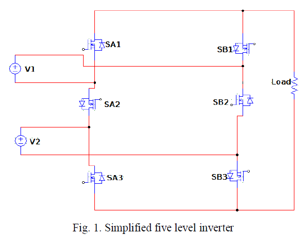
| Single phase simplified five level inverter was proposed by Y. H. Liao is shown in fig. 1. It is derived from two cascaded H-bridge configuration with two switches reduced from the circuit. It consists of six switches arranged in two strings, string A and string B.SA1, SA2 and SA3 are the switches in string A and SB1, SB2 and SB3 are the switches in string B. In string A, source of SA1 is connected to drain of SA2 and source of SA2 is connected to drain of SA3 and vice versa in string B [4]. |
 |
SOLAR CELL MODELING |
 |
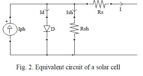 |
| Mathematical equations of a PV cell are given below. |
 |
PROPOSED SYSTEM |
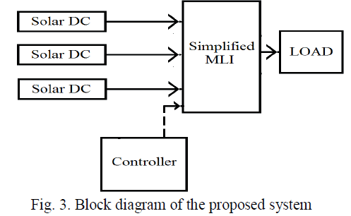
| The proposed solar powered MLI consists of a simplified inverter and three solar powered DC sources. In order to connect three sources, the simplified inverter is extended by adding two more switches in the inverter proposed by Y. H Liao. The block and circuit diagrams are shown in fig. 3 and fig. 4 respectively. |
 |
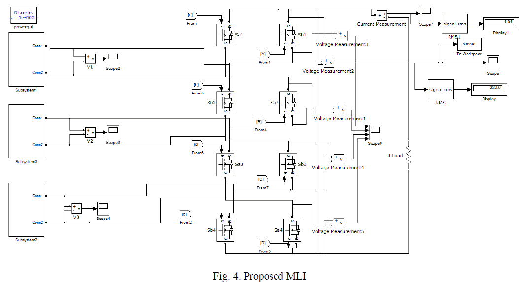 |
| The inverter consists of eight switches arranged in two string format, string A and string B. Sa1, Sa2, Sa3 and Sa4 are the switches in A string and Sb1, Sb2, Sb3 and Sb4 are in B string. The adjacent switches in the string are connected in series with same sides, ie. source-source and drain-drain connections. The positive terminal of the DC source is connected to drain-drain of one string and its negative to source-source of next string. |
A. Boost Converter |
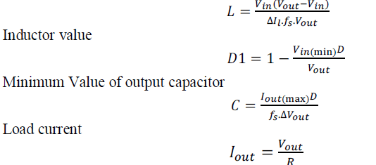
| Figure 5 shows the circuit diagram of a boost converter used in the solar subsystem, which contains an inductor L, controllable switch S/W, diode D, output capacitor C and load resistance R. Boost converter design equation are given below [6]-[7]. |
 |
| Maximum duty cycle |
 |
B. MPPT Technique |
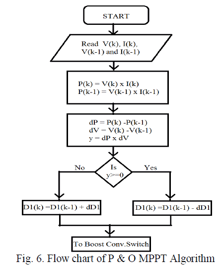
| P & O algorithm or hill climbing technique is used for tracking MPP in the solar system. Figure 6shows the flow chart of the P & O [8]-[9]. |
 |
C. Inverter Controller |
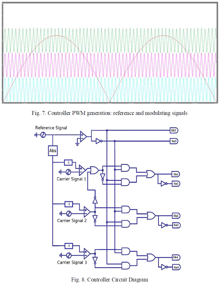
| The PWM switching pulses are used for triggering inverter switches. They are generated using comparison of three triangular carrier waves with rectified sinusoidal modulating signal as shown in fig. 7 and the circuit diagram is shown in fig. 8. |
 |
D. Simulation Results |
| The proposed system is modelled in MATLAB/SIMULINK software. A seven level ac output voltage is obtained from the proposed system is depicted in fig. 9. |
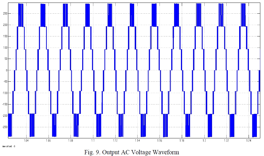 |
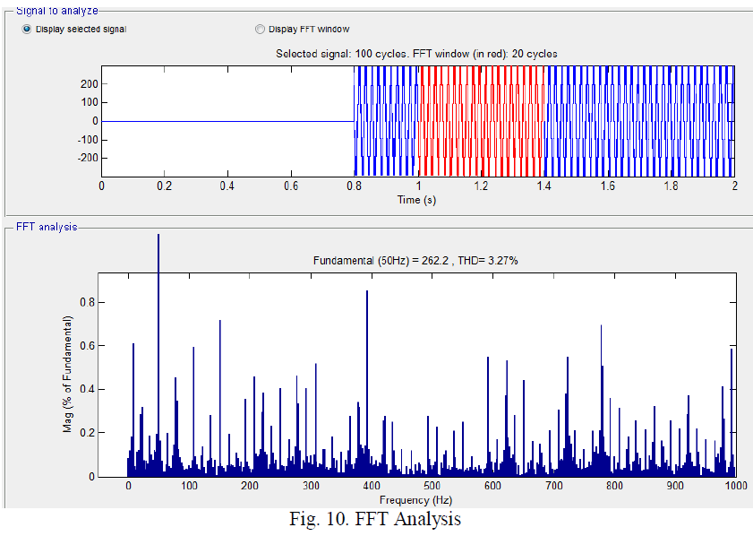
| A 220 V, 50 Hz ac voltage is obtained from the proposed system, at 0.95 modulation index. Fast Fourier Transform (FFT) analysis was conducted on 20 cycles of the ac output voltage, shown in fig. 10, and obtained the fundamental component as 262.2 and THD as 3.27%. |
 |
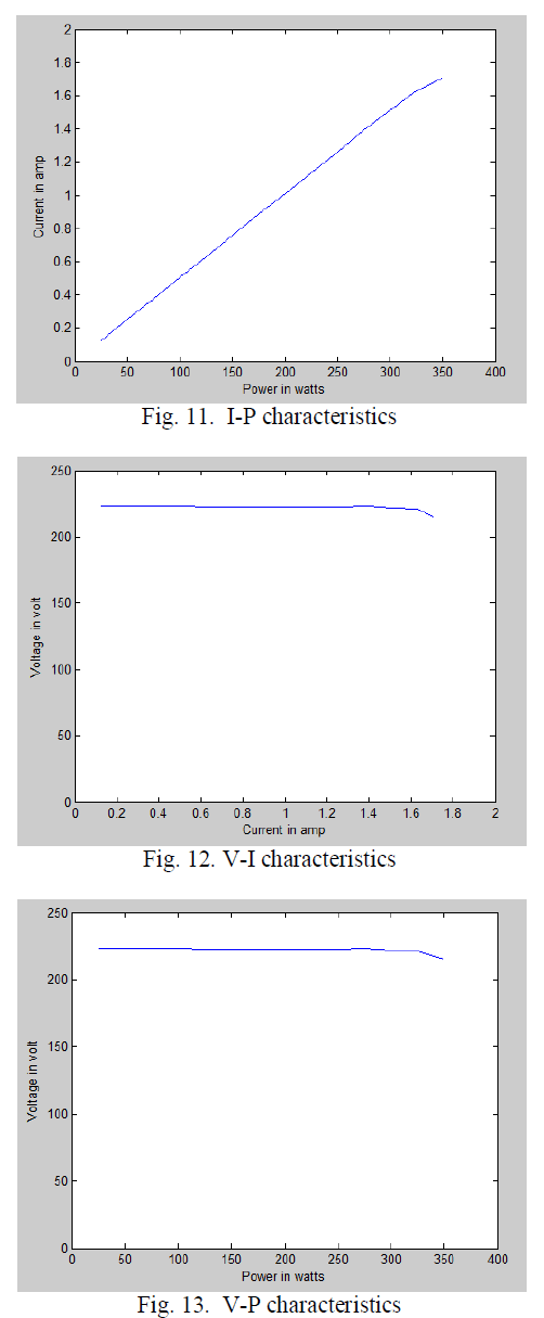
| The current versus power, voltage versus current and voltage versus power characteristics for a variable resistive load are shown in fig. 11, fig. 12 and fig. 13 respectively. The voltage level is almost constant as power or load increases. |
 |
CONCLUSION |
| In this paper, a novel solar inverter system is proposed. A seven level ac output voltage is obtained with few numbers of switches. Size of the proposed 7 level inverter is reduced, in comparison with the existing conventional MLI for attaining same output level. The FFT analysis was conducted on the output ac voltage, which shows very low THD value. I-P, V-I and V-P characteristics shows the stability of this system for a variable resistive load. |
References |
|