ISSN ONLINE(2278-8875) PRINT (2320-3765)
ISSN ONLINE(2278-8875) PRINT (2320-3765)
| Aswathy Vijay1, Binojkumar A.C2 Department of Electrical Engineering, Rajiv Gandhi Institute of Technology, Kottayam, India |
| Related article at Pubmed, Scholar Google |
Visit for more related articles at International Journal of Advanced Research in Electrical, Electronics and Instrumentation Engineering
In this paper, Model Referencing Adaptive Controller (MRAC)based speed and stator resistance estimation of vector controlled induction motor drive ispresented. BothMRACs utilize voltages and currents in synchronously rotating referenceframe anddo not require computation of fluxes. This technique is stable in all four quadrants of operation and also can be used for low speed and zero speed operation. The speed estimation algorithm (i.e., speed estimating MRAS) depends on stator resistance making it sensitive to stator resistance variation.This is compensated by another MRAC making the speed estimation algorithm independent of stator resistance. The proposed method is simulated in MATLAB/SIMULINK and simulation results are obtained
Keywords |
| Induction Motor,Model Referencing Adaptive Controller (MRAC), Stator resistance estimation, Vector control |
 |
INTRODUCTION |
| The Vector controlled inductionmotor (IM) drive is widely used in high performanceindustrial applications since it is simple and provides fastdynamics in terms of the torque response [1] as the independentcontrol of flux and torque can be achieved. The rotor speed can be obtained either by using speed sensors or by estimation. The use of speed sensor [2]-[4] may encounter severalproblems like mounting, signal transmission, hazardousenvironment and reliability. The elimination ofspeed sensor results in reduction of cost and size of the drive, better noise immunity and less maintenance requirements and also increases reliability and robustness of the system. So, the speed estimation ismore preferable than the speed sensing in industrialapplications.On the otherhand, parametersensitivity, stability in the all four quadrants of operation including low and zero speed operation, and high computational effort can bethe main drawbacks of sensor less control. |
| Various techniques are available for the estimation ofspeed for IM drive [1], [5]. These aremainly classified as: (i) Rotor flux based, (ii) Frequency signal injection based, (iii) ModelReference Adaptive System (MRAS) based, |
| (iv)Observer based,(v) Artificial Intelligence (AI)based and (vi) Rotor slot harmonics based methods.Among all these methods, MRAS is simple,requires less computation time and has good stability [5]-[6]. Different types of model reference adaptive system(MRAS) areflux based[4],[7]-[8]back electromotive force (emf) based [10] and reactive power based [9]-[11]. Flux based MRAC and its improved methods[4],[7],[8] efficiently estimate rotor speed in all the four quadrants of operation but it has integrator related problems at very low speed, including zero speed. Back-emf based MRAS [10] is also inefficient at low speed since at low speeds back-emf is very low. A reactive power based MRAS [9]-[11]using instantaneous reactive power in the reference model and steady-state field-oriented reactive power in the adjustable model has no integrators and hence can be used at very low speed including zero speed. This method is independent ofvariation of stator resistance. But in the regenerating mode, the reactive power based MRAS is unstable. |
| HereMRAC called X-MRAC[12],[13],[14] which uses instantaneous value of cross product ofv and i (i.e.,vx i)in the reference model and steady-state flux oriented value of the same in the adjustable model. This MRAC is stable in all the four quadrants, operates very well at low speed including zero speed, does not require flux computation and very easy to implement. However, the formulation involves stator resistancewhich is compensated by another MRAS .This MRAC also,requires only voltages and current in synchronously rotating reference frame for Rs estimation. |
| In the subsequent sections of this paper, the modeling of MRACs, complete system and simulation results are presented |
X MRACBASED SPEED ESTIMATION |
A. X-MRAC |
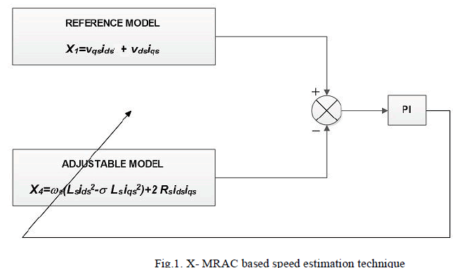
| The structure of the X –MRAC is shown in Fig.1.The cross product of voltage and current in synchronously rotating reference frame is used in the construction of this X -MRAC. This cross product is denoted by X, which is neither active power nor reactive power. In reference model, instantaneous value of X (i.e., X1) is used whereas in adaptive model steady state value of X(i.e., X4)under flux oriented condition is used. The error between the two, E=X1-X4is fed to a PI controller which yields estimated rotor speed. This estimated speed is fed back to adaptive model so that error converges to zero. |
 |
B. Construction of X-MRAC |
| The stator voltages of induction motor in the synchronously rotating reference frame can be expressed as follows |
 |
| The instantaneous value of X(i.e.vx i) is given by |
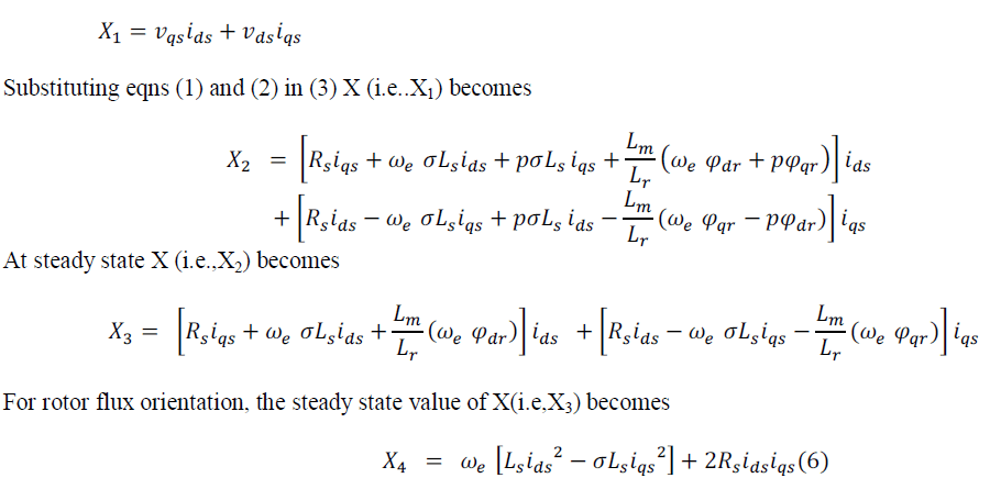 |
| The expression of X1 is independent of rotorspeed. Hence,it is selected for the reference model. X2, X3 or X4can be chosen as the adjustable model since they are dependent on the rotor speed (ωr).However, X4 is selected in the adjustablemodel, as itdoes not require any flux estimation and any derivative operations. But the adjustable model of this MRAS is dependent on stator resistance which may changes during low speed operation. So the stator resistance has to be updated if there is any stator resistance variation. |
STATOR RESISTANCE ESTIMATION |
| The induction motor stator voltages in the synchronously rotating reference frame are given by equations (1) and (2) For a field oriented drive, the simplified expression of voltages atsteady state (i.e., derivative terms, p = 0) becomes: |
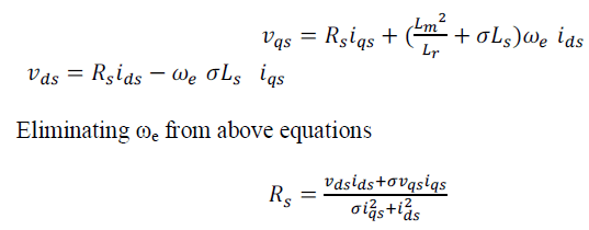 |
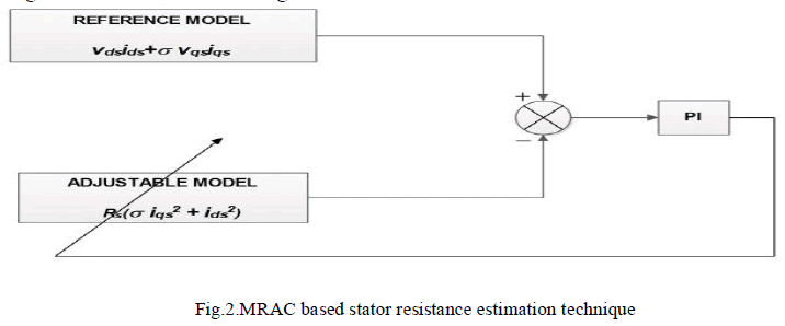
| The above expression is independent of speed. So stator resistance can be estimated usingvoltages and currents in synchronously rotating reference as shown in Fig.2. |
 |
STRUCTURE OF SENSORLESS INDUCTION MOTOR DRIVE |
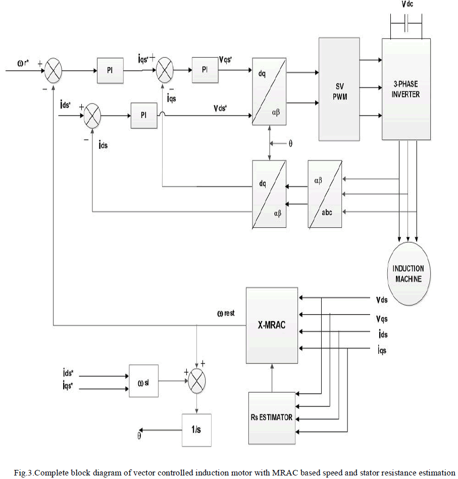
| Entire structure of the MRAS based vector controlled drive is shown in Fig.3. The stator currents are sensed and then transformed from abc to synchronously rotating frame quantities (d-q),ids and iqs,which are the feedback stator currents to current controllers. Stator voltages are also sensed and transformed to synchronously rotating frame quantities (dq). Using thesevoltages and currents in synchronously rotating frame rotor speed is estimated and stator resistance,Rs is updated each time during estimation of rotor speed .The estimated speed is the feedbacksignal to speed controller .Based on feedback signals the control signals are produced which in turn controls the switches of the inverter. |
 |
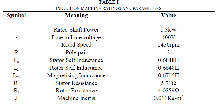
| The complete system shown in Fig.3 is simulated in Matlab/Simulink and this section presents the simulation results. The parameters of the machine are given in the Table I |
 |
A. Step Change of Rotor Speed and Zero Speed Operation |
| The response of the IM for a step change in reference speed and zero-speed operation is shown in Fig.4. The actual speed tracks the reference speed satisfactorily.Fig.4 (a)shows that the estimated speed is very close to the actual rotor speed. Flux orientation is not disturbed, as depicted inFig.4 (b) |
 |
B. Ramp Response |
| The response of the IM to a ramp signal is shown in Fig.5. The estimated speed follows the actual speed as shown in Fig.5 (a) which in turn is matching with the input ramp signal applied.In all these operations, the flux orientation iswell maintainedand can be seen from Fig.5 (b).The results confirmed stable operation in forward and reverse-motoring modes. |
 |
C. Low Speed Operation |
| The performance of theestimator at a low speed of 1rad/s is shown inFig.6.The estimated speed and the actual speed are shown in Fig.6 (a). The flux orientation is maintained, as shown in Fig.6 (b). |
 |
D. Regenerative Operation |
| 1) Second quadrant operation: The second quadrant operation can be seen from Fig.7.The load torque is kept positive at 5 N-m and reference speed is changed from positive to negative and then back to positive which shows the transition of the estimator from motoring to regenerating mode and back. The estimated speed, actual speed follows thereferencespeedasseenfromFig.7(a).The flux orientation is kept samefromFig.7(b) |
2) |
| 3) Fourth quadrant operation: Thefourth quadrant operation can be seen from Fig.8.The load torque is kept at -2 N-m and reference speed is changed from negative to positive and then back to negative which shows the transition of the estimator frommotoringmode to regenerating mode and back. The estimated speed, actual speed follows the reference speed as seen from Fig.8 (a).The flux orientation is kept same from Fig.8(b) |
 |
E. Performance under Resistance Variation |
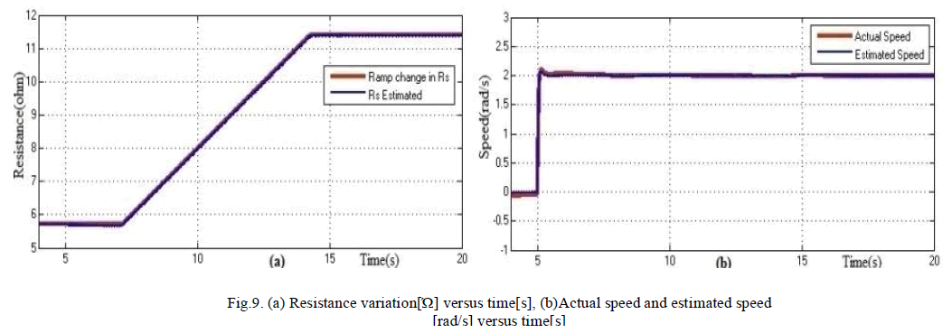
| 1) Motoring Mode: Algorithm is tested for low speed operation considering Rs variation under constant torque as shown in Fig (9). Stator resistance is varied to twice its original value in the form of ramp as shown in Fig 9(a). The estimated speed, actual speed is following the reference speed as shown in Fig. 9(b). Torque is kept constant at 2 N-m. |
 |
| 2) Regenerative mode:Motor speed is changed from +2 rad/s to -2rad/s keeping the torque constant at 5 N-m. The drive is operated in motoring mode up to 10s. Thereafter, it enters in the regenerating mode of operation. The estimated rotor speed is shown in Fig. 10(a). At 14s, Rs ischanged to twice of its original value as shown in Fig. 10(b).The estimator stills works successfully. |
 |
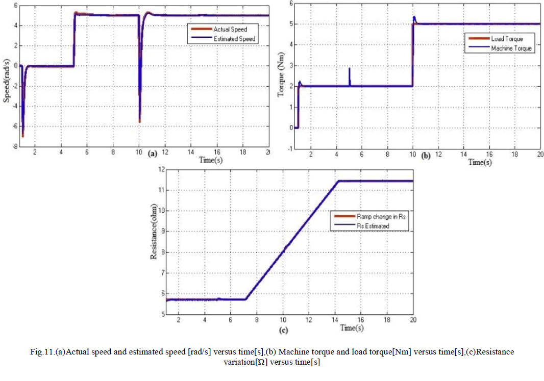
| 3) Performance under load and Rsvariations:Here drive is operated at a speed of 5 rad/sec as shown in Fig. 11(a). A load torque of 2 N-m is applied initially as shown in Fig. 11(b). Now between 7.25s-14.25s Rs is varied to twice of its original value in ramp form Fig. 11(c). During Rs variation(i.e., at 10s)load is increased to5N-m. So from above results it is observed that the drive is stable even load changes during Rsvariation. |
 |
CONCLUSION |
| This paper has presented X-MRAC based speed estimation with stator resistance updation.The X-MRAC based speed estimation technique is stable in all four quadrants of operation and also suitable for low speed and zero speed operation.The adjustable model of X-MRAC depends on stator resistance making the technique sensitive to stator resistance variation.However,another MRAC may be added to X-MRAC based speed estimation to compensate for the variation in stator resistance.Moreover from the simulation results using a 1.3-kW induction motor drive system, it is shown thatthe, speed sensorless drive, thatrequire stator resistance information, can offer better performance with the inclusion of Rs estimation technique.An experimental prototype is under progress. |
ACKNOWLEDGMENT |
| I would like to express my greatest gratitude to the people who have helped and supported me throughout my work. I am grateful to my guide for his continuous support and encouragement for the work. I wish to thank my parents for their undivided support and interest who inspired me and encouraged me to go my own way, without whom I would be unable to complete my work. At last but not the least I want to thank my friends who appreciated me for my work and motivated me and finally to God who made all the things possible. |
References |
|